Functional Description
Microsemi Proprietary and Confidential UG0677 User Guide Revision 9.0 15
3.1.2.1 Serializer
The serializer provides the link between the high-speed interface and the transmit PCS by performing a
parallel-to-serial conversion. Each lane has up to 40-bit data bus to the transmit PCS block and a
separate post-divider for a divide by 1, 2, 4, 8, or 11. The post dividers are provided to divide the high-
speed clock from the TxPLL to exactly what the serializer requires for the data rate. This allows sharing
of a high-speed TxPLL by adjusting the local data rate within the transceiver lane. The glitch-free post-
divider also allows for dynamic switching between dividers and data rates using the APB DRI.
3.1.2.2 Transmit PCS Divider
The PCS divider divides the bit-rate clock from the transmit PLL to a lower rate TX_CLK clock for use in
the fabric. The PMA receives parallel data in the serializer up to 40-bits wide. This divider also sets the
width of the parallel data received from the PCS to 8, 10, 16, 20, 32, 40, 64, and 80 bits. The specific ratio
is a function of the parallel-to-serial or serial-to-parallel conversion in the PMA.
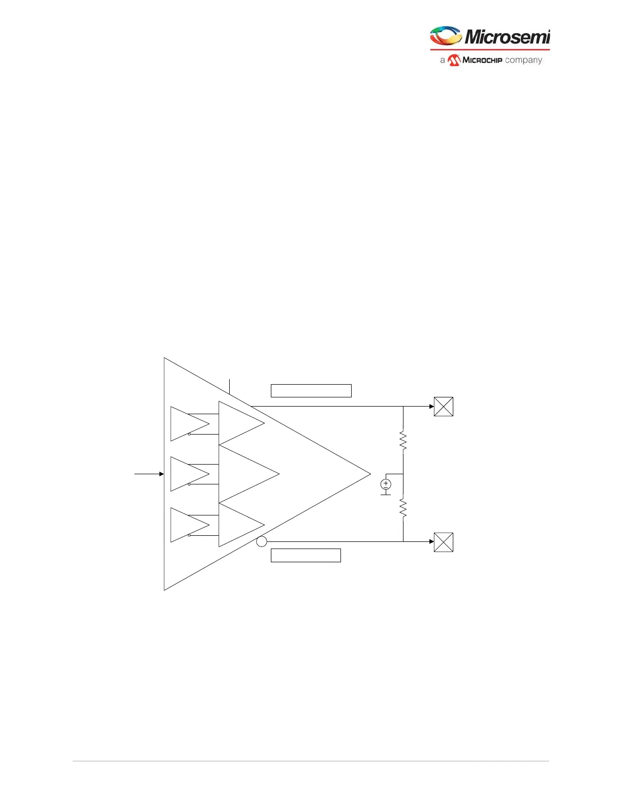
3.1.2.3 Transmit Output Buffer
The following figure shows the transmit output buffer of the transceiver lane, which connects to the PCB
via the XCVR_TXP/N output pins. The low-power H-bridge differential output buffer includes a
configurable driver for amplitude on the 100 differential load up to a maximum swing of 1 V peak to
peak. In addition, selectable levels of transmit common-mode voltage (Tx VCM) are available besides
the swing amplitude control for the output driver segments to control the amount of emphasis. The
transmit output buffer settings are accessible in real-time for adjustment through the JTAG interface
using SmartDebug. It includes a receiver detection to recognize the presence of a physical link. The
output buffer also has electrical idle capabilities used to orderly quiet the link transmitters.
Figure 7 • Transmit Output Driver
Transmit common-mode voltage levels for the drivers are selected by the user during the configuration of
the PMA when using the transceiver configurator in the Libero software. Reducing the transmit output
amplitude lowers the overall transceiver power consumption.
Note: The user can also use a JTAG-based interface from SmartDebug to experiment with transmit settings.
Pre-Cursor
H-Bridge
VDDA
XCVR_TXP
XCVR_TXN
TXCM
Output
Common
Mode
Main Cursor
Post Cursor
Pre-Driver
Pre-Driver
Pre-Driver
PCIe Receiver Detection
Electrical Idle