Implementation
Microsemi Proprietary and Confidential UG0677 User Guide Revision 9.0 87
2. Double-click each PF_TX_PLL block from the catalog to launch the configurator. A GUI allows the
option of selecting the related transmit PLL properties.
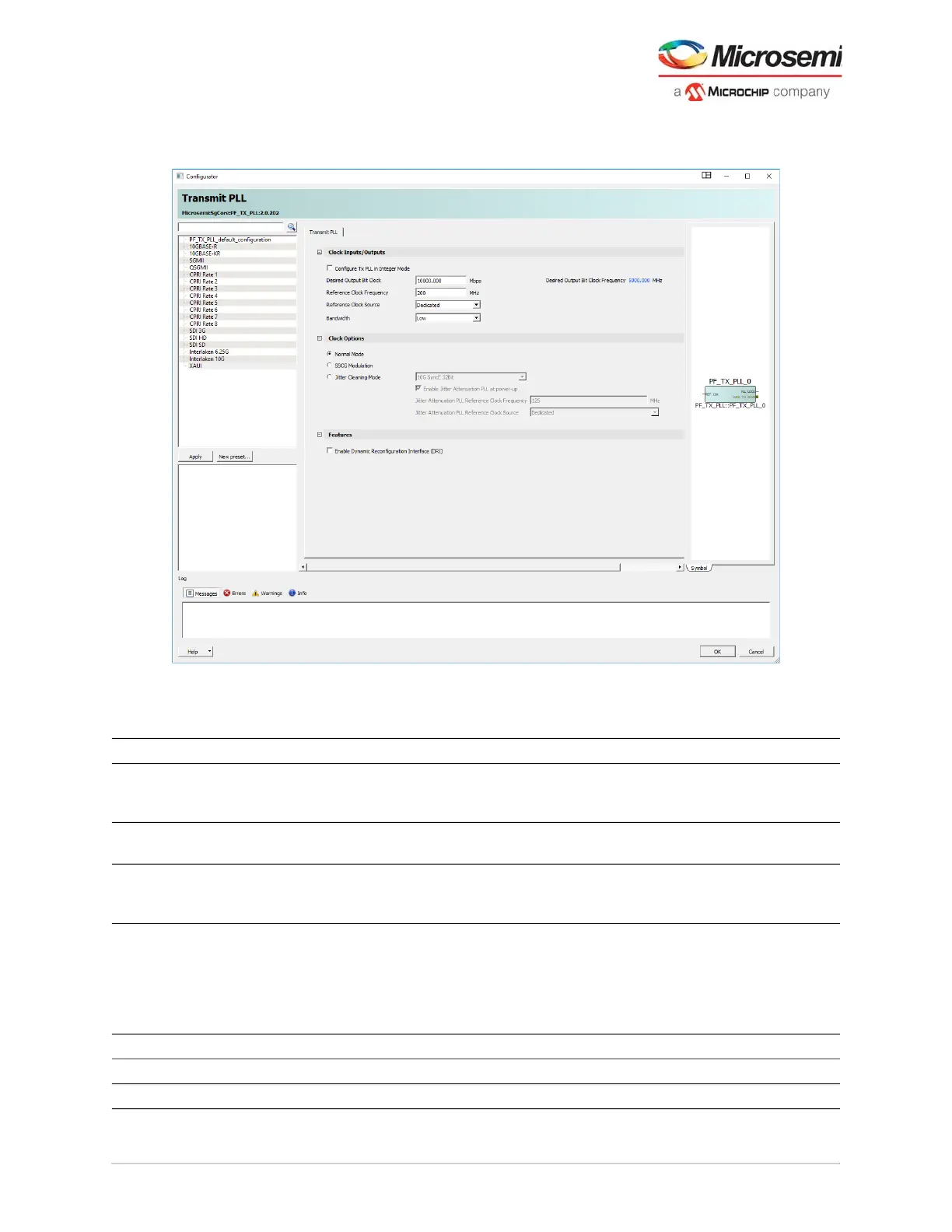
Figure 64 • Transmit PLL Configurator GUI
The following table lists the transmit PLL configurator GUI options.
Table 27 • Transmit PLL Configurator GUI Options
Clock Inputs Options Default Details
Configure Tx PLL in
Integer Mode
Enable and disable Disabled When disabled, it is in TXPLL Fractional N Mode.
When enabled, it allows fixed value of available
reference clock frequencies.
Reference Clock Source Dedicated and fabric Dedicated Dialogue box requires input clock rate (200 MHz
default)
Desired Output Bit Clock VCO rate, and output
clock (MHz)
10000 Mbps,
5000 MHz
Only valid combinations can be entered based on
reference clock and PLL capability. This value
represents the BIT_CLK output speed.
Bandwidth Low/High Low By default, the Tx PLL selects the low bandwidth
option in order to filter more of the reference clock
jitter. If the system has a low-jitter reference clock,
the user can then set it to high bandwidth mode to
decrease the overall jitter. Low bandwidth has longer
lock times than high bandwidth.
Clock options (Only one option can be selected)
Normal Mode Enable and disable Enabled Radio-button on = enabled
SSCG Modulation Enable and disable Enabled Radio-button on = disabled