Signal Integrity Conditioning
Microsemi Proprietary and Confidential UG0677 User Guide Revision 9.0 117
5.4.1 Loopback Modes
Loopback operations are embedded within the PolarFire XCVR and are commonly used in debug
practice. These loop backs can be tested solely within the device by sending and receiving on-chip or
can test real-data to and from the system side. For information, see Loopback, page 122.
For example, by placing the transceiver into EQ Far-End loopback, a system can drive data into the Rx
and send it back directly onto the Tx. In this case, the system is passing the serial data stream within the
input and output buffers. Change the Signal Integrity panel settings to find the optimal setting to match
the system.
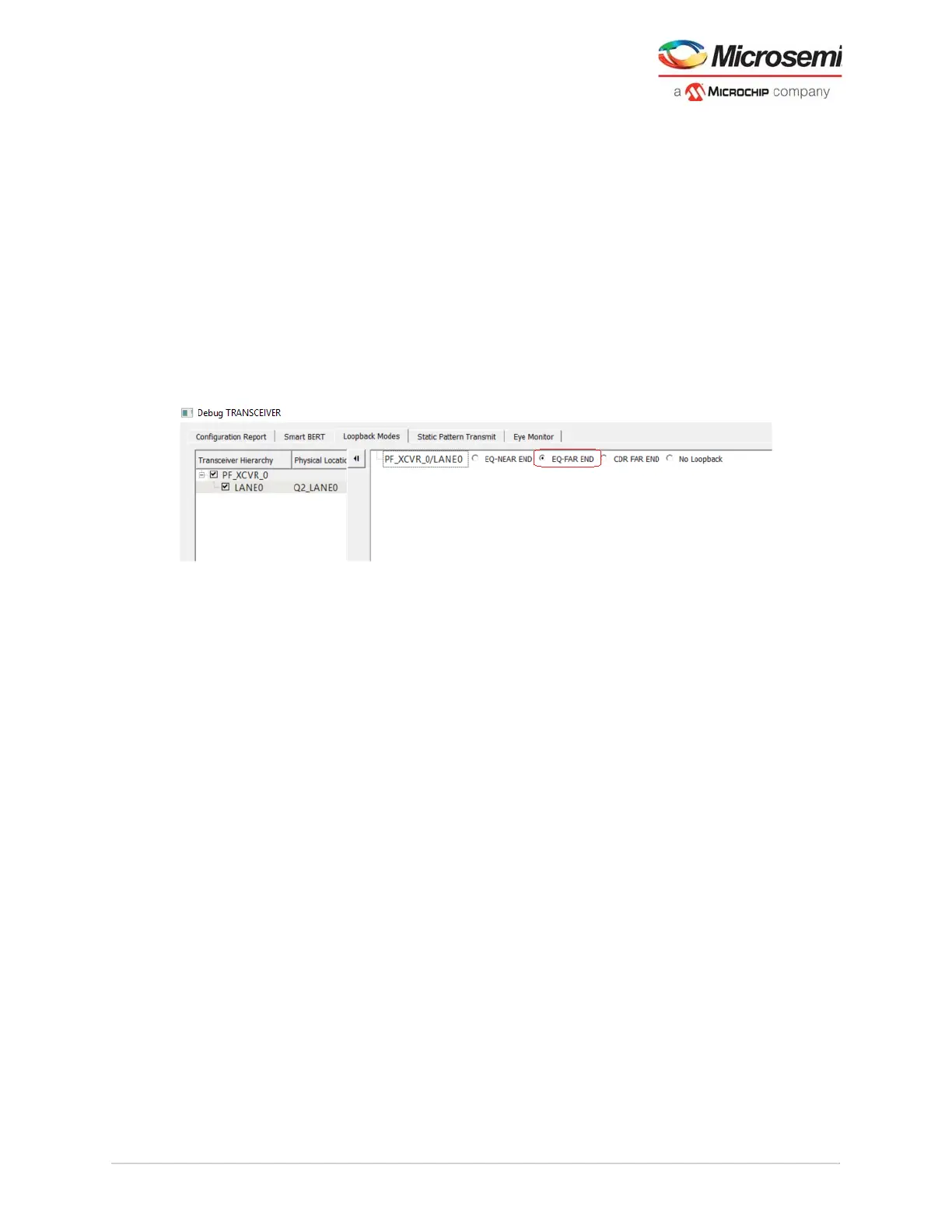
In the Loopback Modes tab, select the targeted lane to test under Transceiver Hierarchy, select EQ-
FAR END and then click Apply to monitor the system performance from the far-end. Adjust the signal
integrity setting to optimize the Rx and Tx performance of the PolarFire transceiver. The following figure
shows the loopback modes of the Debug TRANSCEIVER.
Note: The Apply button is enabled when you make a selection for any parameter.
Figure 94 • Loopback Modes—Far-end Example
Similarly, the user can also continue to test a deeper path into the PolarFire XCVR path using CDR Far-
end loopback. In this manner, the same system data stream would pass from the input buffer through the
Rx PMA and the parallel data stream would be routed back through a pathway to the Tx PMA to the
output buffer.
5.4.2 SmartBERT
The CoreSmartBERT IP core provides a broad-based evaluation and demonstration platform for
PolarFire transceivers (PF_XCVR). See HB0788: CoreSmartBERT Handbook (download the handbook
from Libero Catalog). For any transceiver design, PRBS tests from XCVR PMA are available by default.
SmartBERT enables you to run diagnostic tests on the transceiver lanes. The self-testing capability can
be used for isolating faults either during development debug or for in-field diagnostics using the
transceiver built-in PRBS generator and checker.
SmartBERT uses the PRBS generator and checker functionality available in each transceiver lane to
determine the bit error rate (BER) of a lane. The various PRBS patterns supported are PRBS7, PRBS9,
PRBS15, PRBS23, and PRBS31. Near-end loopback can be performed using one of these PRBS
patterns. Bit Error Rate (BER) displays the BER for the PRBS test in progress.
To run a PRBS pattern:
1. Select one of the Patterns from the drop-down list.
2. Select the EQ-NearEnd check box. When checked, the selected lane gets added to the right hand
side where PRBS test can be performed. When unchecked, the selected lane gets removed from
the added list (see Figure 96, page 118).
3. Click Start in the bottom-left corner of the window. The loopback cycle is initiated and the result is
displayed. It enables both transmitter and the receiver for a particular lane and for a particular PRBS
pattern.The GUI shows the status of the TXPLL, RXPLL, Lock to Data, Data rate, and the BER
(see Figure 96, page 118).
4. Click Stop in the bottom-right corner of the window to stop the loopback.