3. Cut pin to calculated length “L”.
L = AD - AC + DE + 3.05 (0.012)* +0.02 (0.0008)** [mm (in.)]
L = overall length from tip to top of pin head
* 3.05 = head of pin
** 0.02 = pressure preload
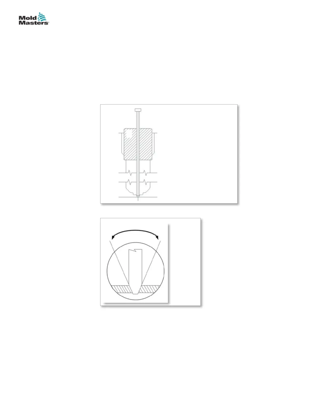
4. Grind the valve pin tip an angle of 20° per side (40° inclusive).
5. Lap the tip of the pin into the land area (steel section in the gate area)
using a lapping guide bushing or valve bushing as a lapping guide. We
recommend 400 - 600 grit lapping paste.
1
2
3
4
5
1. Nozzle ange bore
2. Machined bushing for center
alignment
3. Nozzle / angled valve pin
4. Nozzle well bore
5. Cavity
Figure 10-10 Bushing for pin tip
40°
1
1
2
1. Land area
2. Cavity face
Figure 10-11 Land location
5500 Series - continued
10-5HYDRAULIC / PNEUMATIC ACTUATORS
Hot Runner User Manual
© 2020 Mold-Masters (2007) Limited. All Rights Reserved.