Section 5 - Assembly
WARNING
Ensure that you have fully read “Section 3 - Safety” before assembling
parts of the Hot Runner system.
This section is a step-by-step guide to assembling your Mold-Masters Hot
Runner system.
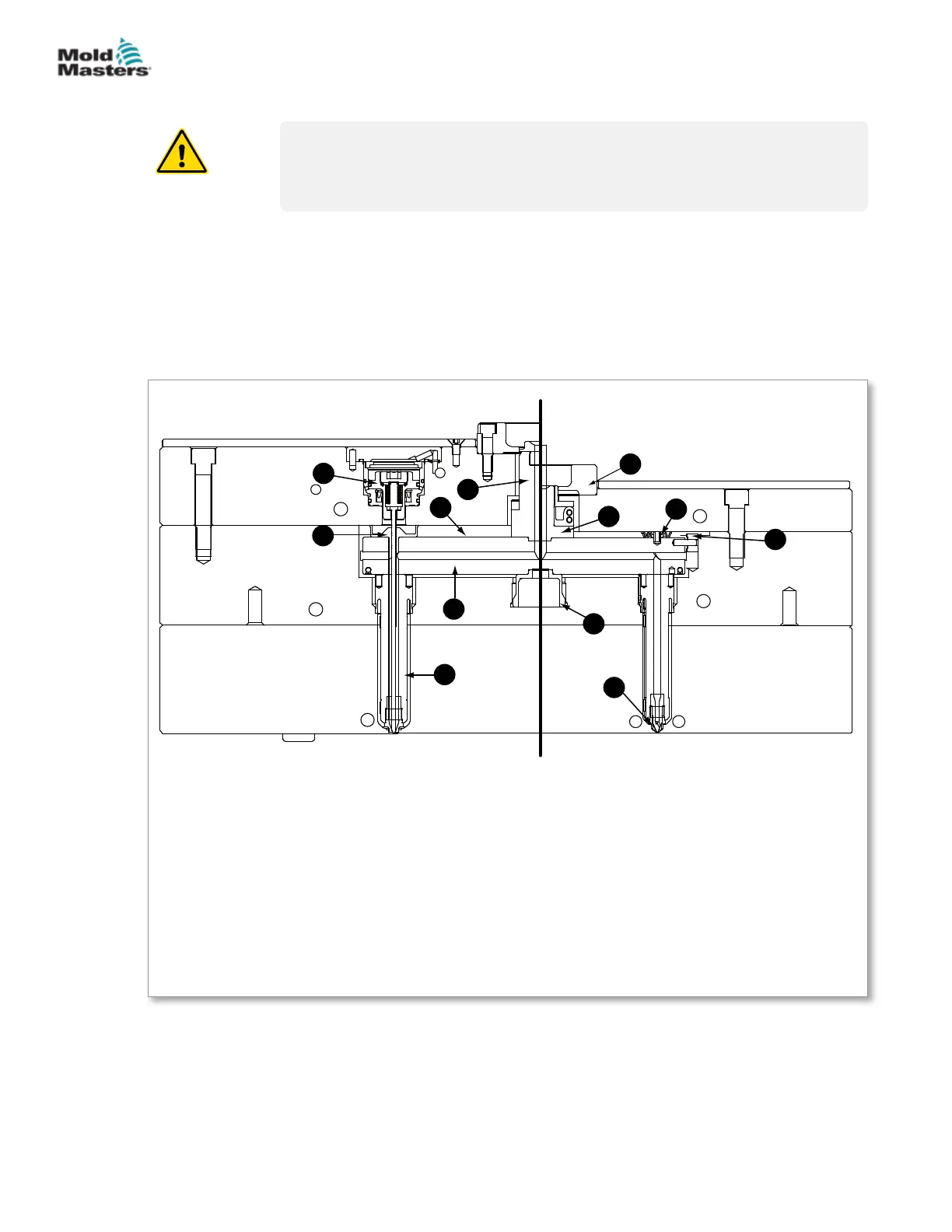
5.1 Cutaway of a Cast-in System
This illustration of a typical Mold-Masters cast-in Hot Runner system is
divided into two halves: valve side and non-valve side. The terminology
associated with the various components and features are listed below.
Figure 5-1 Cutaway - cast-in system
Valved
12
2
7
3
6
4
9
5
11
1
8
10
Non-Valved
Hot Half - Cast In Arrangement
1. Air gap
2. Inlet extension
3. Locating ring
4. Machine nozzle pad
(backplate)
5. Manifold locating cam
6. Manifold locator
7. Cast-in manifold
8. Nozzle
9. Pressure disk
10. Gate seal
11. Valve actuator
12. Valve disk
5-1ASSEMBLY
Hot Runner User Manual
© 2020 Mold-Masters (2007) Limited. All Rights Reserved.