5.16.2 Inlet Seal Installation - With Step
Manifolds that use inlet seals with a step:
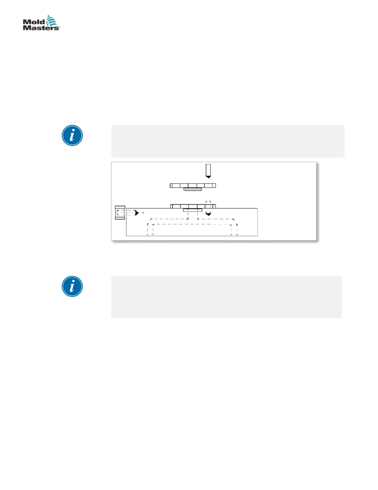
1. Install the step inlet seal to the manifold.
2. Install the dowel pin into the seal and manifold.
3. Lower the main manifold into position.
4. Install manifold mounting screws and torque to required settings.
Refer to your General Assembly drawing for specications.
5. Install the manifold thermocouples. Refer to “5.15 Manifold Thermocouple
Installation”.
NOTE
On bridge manifold systems, mounting screws should be torqued 1/3 higher
than specied on General Assembly drawings.
3
2
1
1. Submanifold
2. Inlet seal
3. Locating dowel
Figure 5-25 Inlet seal with step
5.17 Pressure Disk / Valve Disk Installation
NOTE
Pressure disks are not used within ThinPAK-Series systems. Please see
“Support Bushing Installation for Systems with MasterSHIELD” on page
5-42.
Review your parts list and General Assembly drawing to determine the
feature installed in your system.
• Pressure Disk - is compressed by thermal expansive forces to form
part of the plastic sealing mechanism. This also helps to reduce thermal
transfer to a minimum. These may or may not require grinding.
• Valve Disk - is compressed by thermal expansive forces to form part of
the plastic sealing mechanism. Its high tolerance bore allows the valve
pin to shift through it without plastic leakage and part of it enters the melt
stream and helps guide the plastic ow without stagnation. These may or
may not require grinding.
For additional information please refer to “4.5 Establish Your System Type”.
5-35ASSEMBLY
Hot Runner User Manual
© 2020 Mold-Masters (2007) Limited. All Rights Reserved.