3. Apply anti-seize compound to the retaining screw and secure the
thermocouple with the screw.
19.4.6 Melt-CUBE Design B: Attach the Ground Wire
1. Apply anti-seize compound to the retaining screw.
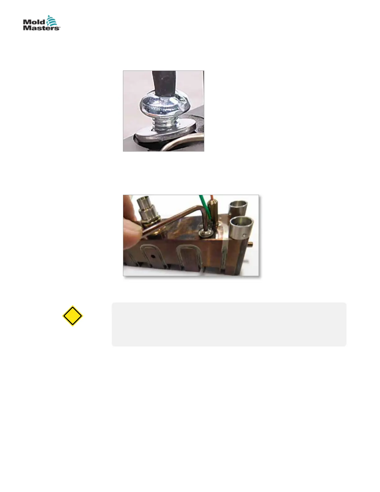
2. Secure the ground wire with the retaining screw. See Figure 19-14.
Figure 19-14 Secure the ground wire
Melt-CUBE Design B: Install the Thermocouple -
continued
19.4.7 Melt-CUBE Design B: Install the Melt Transfer Link
CAUTION
This procedure must be done with the Melt-CUBE at room temperature,
between 10°C and 40°C (50°F and 104°F).
Melt transfer links must also be torqued within this temperature range.
CAUTION
1. Apply anti-seize compound to the threads on the top and bottom halves of
the melt transfer link.
19-23MELT-CUBE SYSTEMS
Hot Runner User Manual
© 2020 Mold-Masters (2007) Limited. All Rights Reserved.