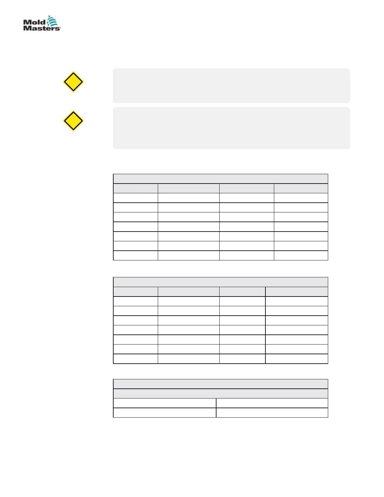
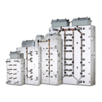
15.14.6 System and Plate Screw Torques
Torque sequence and step torquing: We recommend that system screws be
torqued in a standard bolt pattern and that the specied torque be achieved in
3 steps (1/3, 2/3 and full torque).
CAUTION
Bridge manifold mounting screws should be torqued 1/3 higher than
specied on General Assembly drawings.
CAUTION
CAUTION
For systems with MasterSHIELD, tighten the system screws from the center
outward to exert an even load across all screws during assembly. Tighten
the screws to the specied torque in a minimum of two steps.
CAUTION
Quality and length of screws must be as specied on Mold-Masters General
Assembly drawings.
Table 15-9 Torque Chart for System Assembly Screws
Metric Torque Setting Imperial Torque Setting
M5 7 Nm #10-32 5 ft lbs
M6 14 Nm 1/4-20 10 ft lbs
M8 20 Nm 5/16-18 15 ft lbs
M10 40 Nm 3/8-16 30 ft lbs
M12 60 Nm 1/2-13 45 ft lbs
M16 145 Nm 5/8-11 107 ft lbs
M20 285 Nm 3/4-10 210 ft lbs
Table 15-10 Torque Chart for Plate Assembly Screws
Metric Torque Setting Imperial Torque Setting
M5 9 Nm / 6 ft lbs #10-32 7 Nm / 5 ft lbs
M6 15 Nm / 11 ft lbs 1/4-20 16 Nm / 12 ft lbs
M8 36 Nm / 27 ft lbs 5/16-18 33 Nm / 24 ft lbs
M10 72 Nm / 53 ft lbs 3/8-16 59 Nm / 44 ft lbs
M12 125 Nm / 92 ft lbs 1/2-13 144 Nm / 106 ft lbs
M16 311 Nm / 229 ft lbs 5/8-11 287 Nm / 212 ft lbs
M20 606 Nm / 447 ft lbs 3/4-10 511 Nm / 377 ft lbs
Table 15-11 Component Torque Settings
Valve Actuator
Series 5500, 6500, 6600 and 6700 Torque Setting
Piston Top 20-27 Nm (15-20 ft-lbs)
15-26
© 2020 Mold-Masters (2007) Limited. All Rights Reserved.
MAINTENANCE
Hot Runner User Manual


 To Next Page