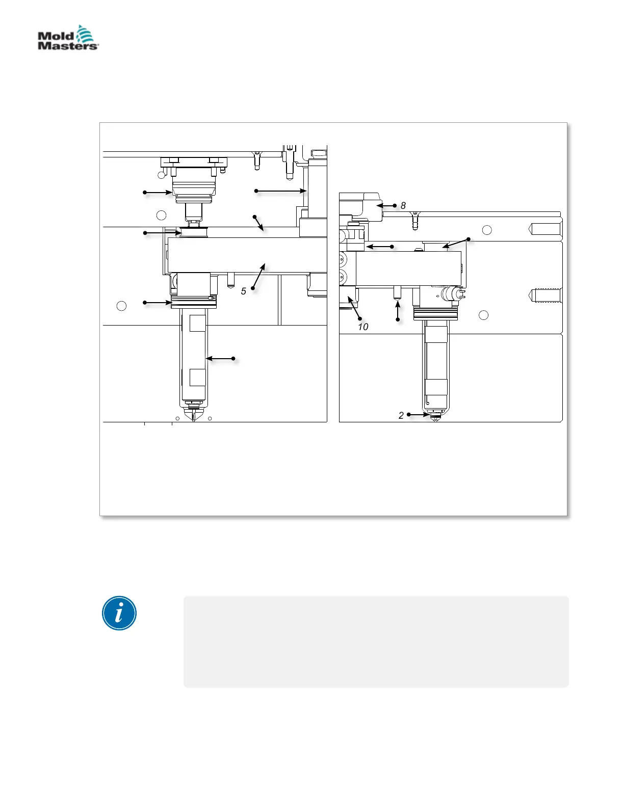
5.3 Cutaway of a MasterSHIELD System
This illustration of a typical Mold-Masters MasterSHIELD cast-in system
is divided into two halves: the valve side and the non-valve side. The
terminology associated with the various components and features are listed
below.
1. Valve actuator
2. Valve disk
3. Spring
4. MasterSHIELD
nozzle
5. Manifold
6. Air pocket
7. Inlet extension
8. Locating ring
9. Machine nozzle pad (backplate)
10. Manifold locator
11. Manifold anti-rotation dowel
12. Gate seal
13. Support pad
Figure 5-3 Cutaway of a MasterSHIELD cast-in system
Valved
1
2
3
4
5
6
7
Non-valved
8
9
10
11
12
13
5.4 Gate Seal Finishing
Most nozzles are supplied with the gate seal installed except when the seal
requires nal machining by a toolmaker, such as the hot valve or hot sprue.
NOTE
The gate seals supplied with your system may need to be adjusted to
tolerances based on the material grade and cooling in the cavity. Refer to
your Mold-Masters General Assembly Gate Detail drawing to determine if
gate seal nishing is required. Refer to the General Assembly drawing to
determine which gating method applies.
5-3ASSEMBLY
Hot Runner User Manual
© 2020 Mold-Masters (2007) Limited. All Rights Reserved.