19.3.8 Melt-CUBE Design A: Assemble Melt Transfer
Link to Melt-CUBE
CAUTION
Melt transfer links must be torqued at room temperature, between 10°C and
40°C (50°F and 104°F).
CAUTION
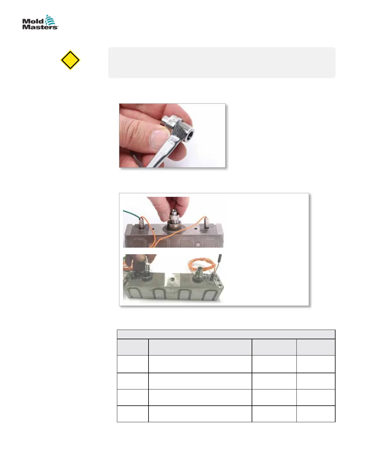
1. Apply anti-seize compound to the threads of the melt transfer link (top half
and bottom half).
2. Thread the melt transfer link bottom half into the Melt-CUBE and the melt
transfer link top half into the nozzle.
Standard Melt-CUBE system
Dual nozzle Melt-CUBE
system
3. Torque the melt transfer link to the value specied in the torque chart or
the General Assembly diagram. See Caution above.
Table 19-1 Melt-CUBE Design A: Melt Transfer Link Torque Chart
Part
Number
Description
Torque Value
Nm (ft-lb)
Socket
Size (mm)
MTL015A Melt Transfer Link Deci Top Half
(to nozzle)
34-38
(25-28)
19
MTL016A Melt Transfer Link Centi Top Half
(to nozzle)
27-30
(20-22)
16
MTL015B Melt Transfer Link Deci Bottom Half
(to Melt-CUBE)
27-30
(20-22)
17
MTL016B Melt Transfer Link Centi Bottom Half
(to Melt-CUBE)
27-30
(20-22)
15
19-8
© 2020 Mold-Masters (2007) Limited. All Rights Reserved.
MELT-CUBE SYSTEMS
Hot Runner User Manual