5.21 Inlet Components Installation
CAUTION
For all inlet components it is important that the mold locating ring is
touching the inlet component just enough for sealing the area. This should
be double checked with the system drawings.
CAUTION
The following procedures refer to dierent system congurations. Refer to
your parts list and General Assembly drawings to determine your system
type.
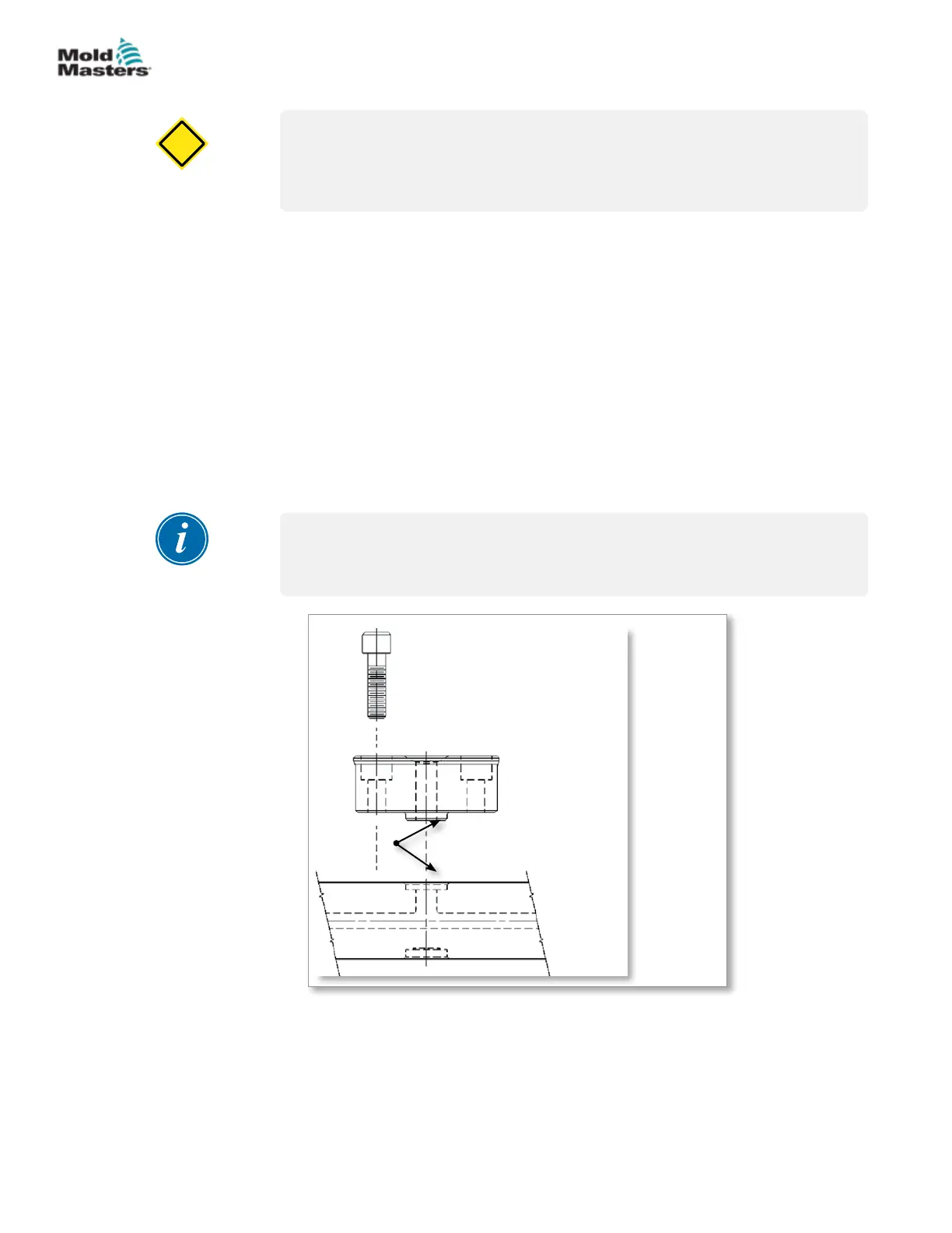
5.21.1 Back Plate Installation
1. Check the machine nozzle radius.
2. Check the seating on the bottom face of the back plate and manifold.
3. Install the back plate onto the manifold.
4. Install M8 mounting screws through the back plate to the manifold using
anti-seize compound on threads.
5. Torque screws to value indicated on the General Assembly drawing in a
cross pattern, in 7 Nm (5 lbf-ft) increments.
NOTE
The machine nozzle bore should be no less than 1.0 mm (0.040 in.) smaller
than the back plate bore and no larger than the back plate bore.
1
2
3
4
5
1. Mounting screw
2. Nozzle radius
3. Back plate
4. Manifold
5. Bottom face
Figure 5-39 Back plate installation
5-46
© 2020 Mold-Masters (2007) Limited. All Rights Reserved.
ASSEMBLY
Hot Runner User Manual