5.17.5 Valve Disk - Final Grinding Required
These valve disks are supplied with stock allowance (oversized in height),
and they require grinding to the nal dimension specied on the system
General Assembly drawing.
1. Grind the valve disk on top side only.
2. Remove sharp corners after grinding and clean the valve disk, especially
inside the valve pin bore.
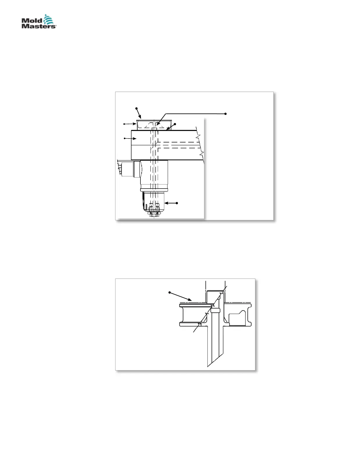
1
2
4
3
Clean bore after
grinding
Ensure correct air gap as per General
Assembly drawing
1. Spring dowel
2. Nozzle
3. Manifold plate
4. Valve disk
Figure 5-32 Manifold to nozzle mounting
3. Install the manifold to the nozzle.
4. For 1-piece valve disk - Install the valve disk in appropriate orientation.
For 2-piece valve disk - Insert valve stem into the manifold in appropriate
orientation. Slide valve disk ange over the stem. See Figure 5-33.
Ensure correct air
gap as per General
Assembly drawing
1
2
1. Valve disk ange
2. Valve disk stem
Figure 5-33 2-piece valve disk
5. Ensure correct air gap between the valve disk and the top plate as
specied in the General Assembly drawing.
6. For information on removal, refer to “15.1 Valve Disk Removal” on page
15-1.
5-40
© 2020 Mold-Masters (2007) Limited. All Rights Reserved.
ASSEMBLY
Hot Runner User Manual