5.20 Heater Plates Installation
CAUTION
Heater plates are controlled by a thermocouple located in the heater plate.
Do not control the heater plate from a thermocouple in the manifold.
Use caution to not pinch or damage the thermocouple.
Do not overtighten the mounting screws. This could result in the heater
plate losing contact with the manifold plate.
Refer to the General Assembly drawing for the correct torques.
CAUTION
NOTE
Current bronze heater plates are directly interchangeable with previous
copper or aluminum based plates that may exist on your Mold-Masters
system.
However, when multiple heater plates are controlled by one thermocouple,
these heater plates must be made of the same material, be of equal wattage
and be located in similar thermal environments.
These procedures apply to systems with external heater plates. Refer to the
General Assembly drawing to determine which heater plate applies to your
system.
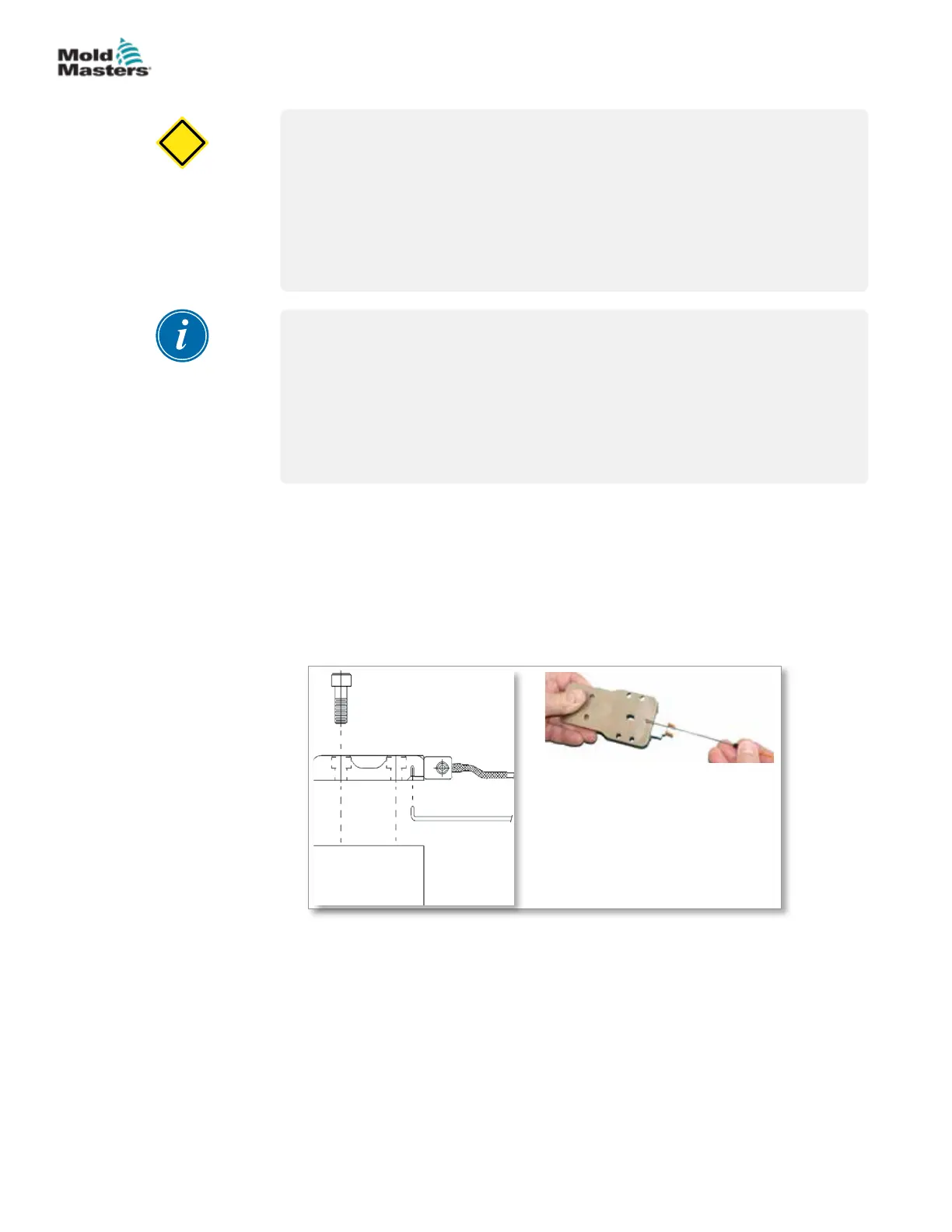
1. Clean the thermocouple bore. Suggestion for 1.5 mm (0.06 in.)
thermocouples is to use a 1/16 inch drill in a pin vise.
2. Insert the thermocouple into the bore. Ensure the thermocouple is
touching the bottom of the bore hole.
1
2
3
4
5
1. Thermocouple
2. Manifold
3. Mounting screw
4. Heater plate
5. Thermocouple bore hole plate
Figure 5-37 Thermocouple installation
3. Press down on the thermocouple and gently bend to 90°.
4. Secure the heater plate to the manifold. Refer to the General Assembly
drawing for location. Use anti-seize compound on the threads.
5-44
© 2020 Mold-Masters (2007) Limited. All Rights Reserved.
ASSEMBLY
Hot Runner User Manual