17.5 Assembly of Accu-Line™ with Valve Insert
CAUTION
Verify the stroke height stated on the General Assembly drawing before and
after installing the cylinder top in the assembly.
CAUTION
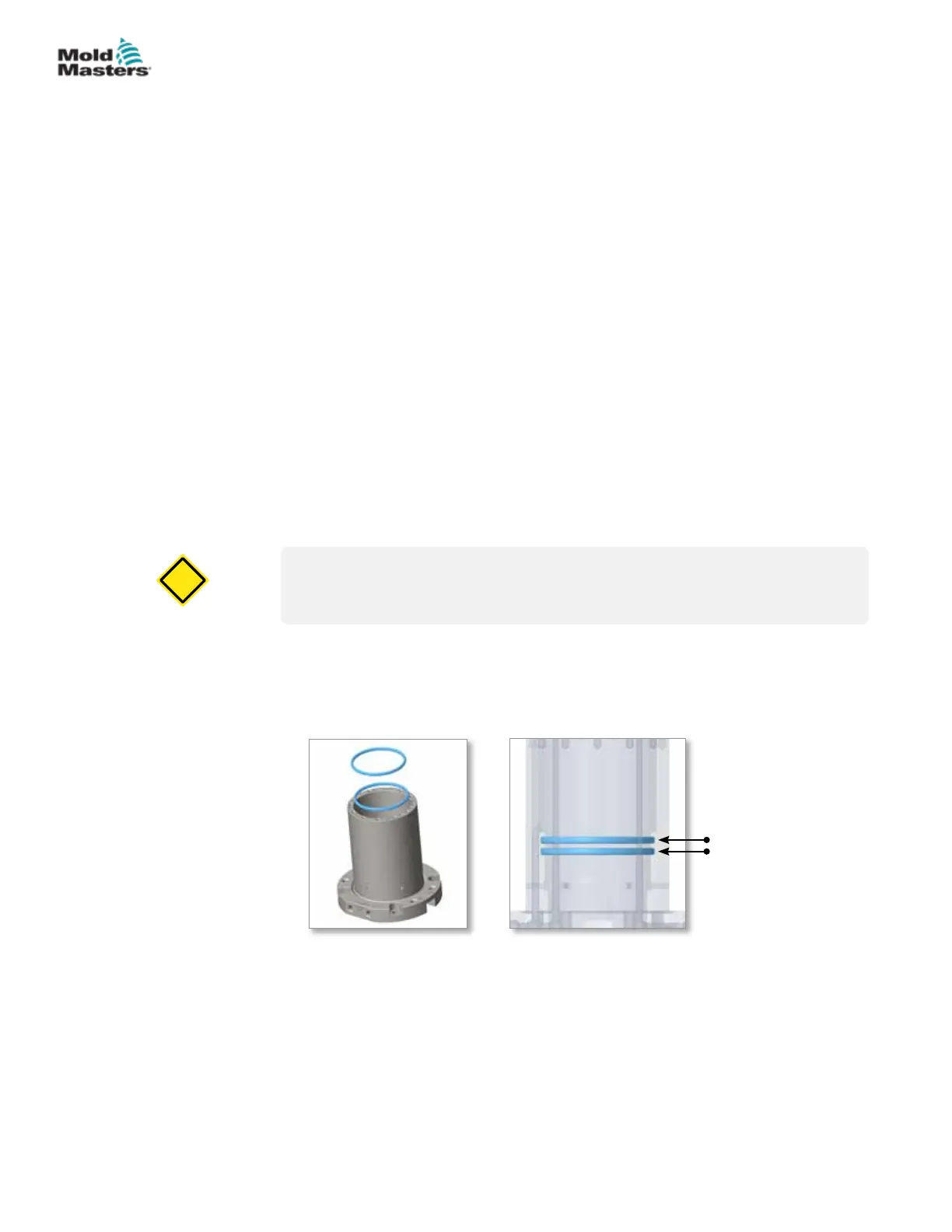
1. Apply grease to the rod seal and guide ring grooves in the inner surface
of the cylinder.
2. Use your ngers to gently push the rod seal and guide ring into the
grooves in the cylinder. Make sure that both sit rmly in the grooves.
22
23
22.Guide ring
23.Rod seal
A. Outer cylinder
B. Heated body
C. Cylinder top
D. Piston
E. Cover plate
F. Insulation plate
G. Valve pin holder
H. Nozzle
I. Adapter
J. Gate seal
K. Ground wire
L. Socket head cap screw
M. Shoulder screw
N. Dowel pin
O. Valve insert
P. Inlet tip
Q. Jiy plug
R. TC retaining cap
S. Support sleeve
T. Hose
U. Guide ring
V. Guide ring
W. Guide ring
X. Valve pin
Y. Rod seal
Z. Rod seal
AA. O-ring*
AB. O-ring*
*O-ring kit ORIA18KIT consists of these parts.
17-11ACCU-LINE™
Hot Runner User Manual
© 2020 Mold-Masters (2007) Limited. All Rights Reserved.


 To Next Page