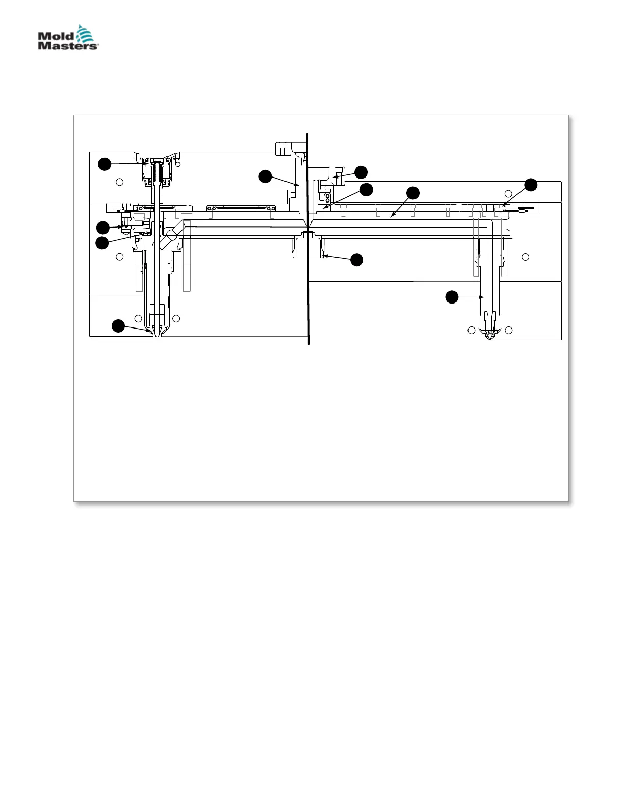
5.2 Cutaway of a Bolt-in System
This illustration of a typical Mold-Masters bolt-in Hot Runner system is divided
into two halves: the valve side and the non-valve side. The terminology
associated with the various components and features are listed below.
Valved Non-Valved
Hot Half - Bolt In Arrangement
3
5
6
1
10
11
9
7
2
8
4
1. Manifold locating cam
2. Bolt-in manifold
3. Gate seal / gate insert
4. Heater plate
5. Inlet extension
6. Locating ring
7. Machine nozzle pad (backplate)
8. Manifold locator
9. Nozzle
10. Valve actuator
11. Valve bushing\
Figure 5-2 Cutaway of a bolt-in system
5-2
© 2020 Mold-Masters (2007) Limited. All Rights Reserved.
ASSEMBLY
Hot Runner User Manual