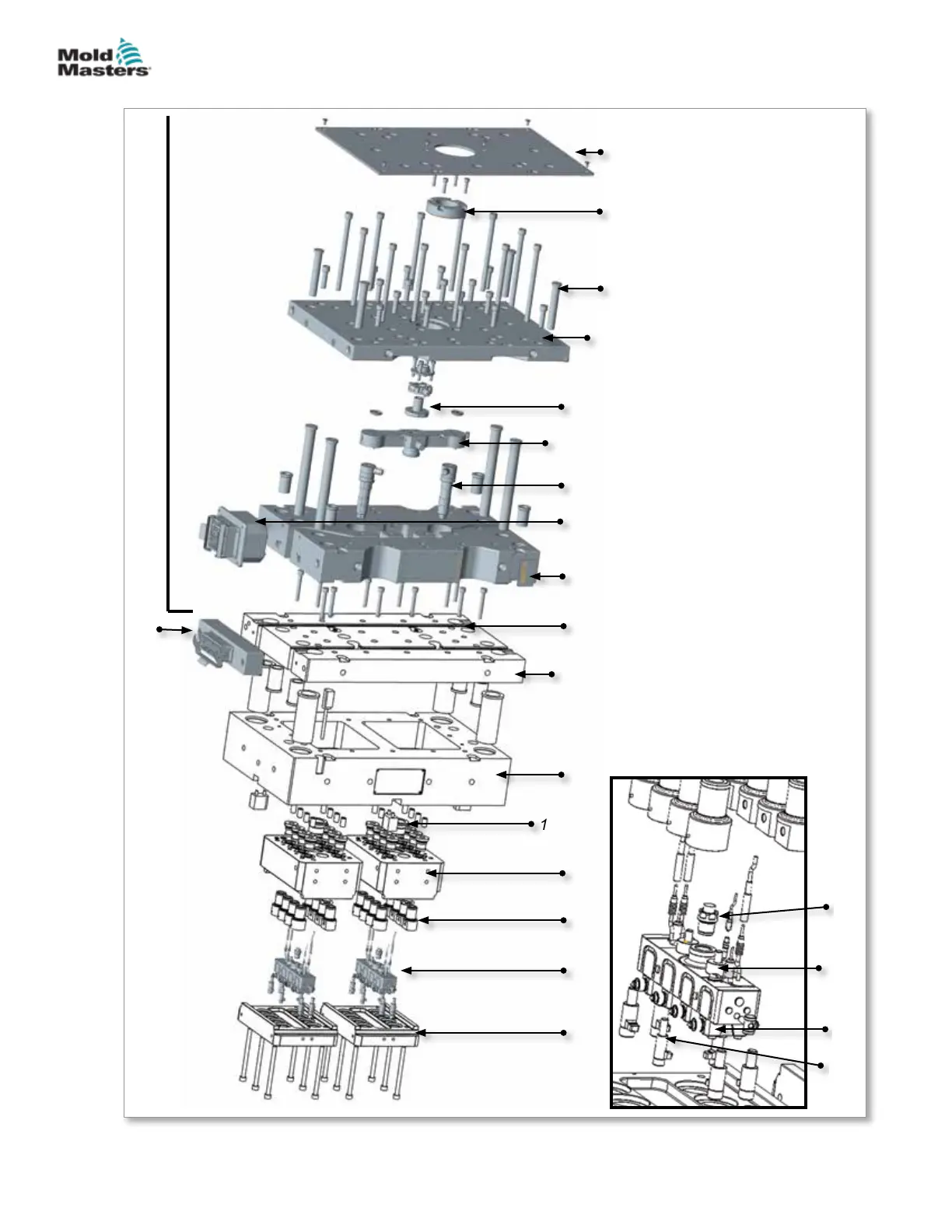
Figure 19-3 Melt-CUBE system - example
21
22
19
Melt-CUBE assembly
20
11
13
15
16
1
2
3
9
4
5
6
7
17
18
12
8
10
SEE “Section 5 - Assembly”
14
1. Insulation plate
2. Locating ring
3. Leader pins
4. Top clamp plate
5. Inlet
6. Bridge / manifold
7. Nozzle
8. Heater, nozzle, electrical
box
9. Manifold plate
10. Wire channel
11. Cavity backing plate
12. Melt-CUBE electrical box
13. Cavity plate
14. Melt-CUBE center locator
15. Cavity block
16. Cavity inserts
17. Melt-CUBE assembly
18. Cavity block cover plate
19. Melt transfer link
20. Melt-CUBE
spacing
supports
21. Melt wedge
22. Clamp
19.2 Example of a Melt-CUBE System
19-3MELT-CUBE SYSTEMS
Hot Runner User Manual
© 2020 Mold-Masters (2007) Limited. All Rights Reserved.


 To Next Page