10.7 Valve Pin Lapping Procedure for Tapered
Valve Pins
10.7.1 5500 Series and 6X00 Series
WARNING
Avoid skin contact with decomposing O-rings. Use appropriate protective
clothing. Failure to do so can cause serious injury.
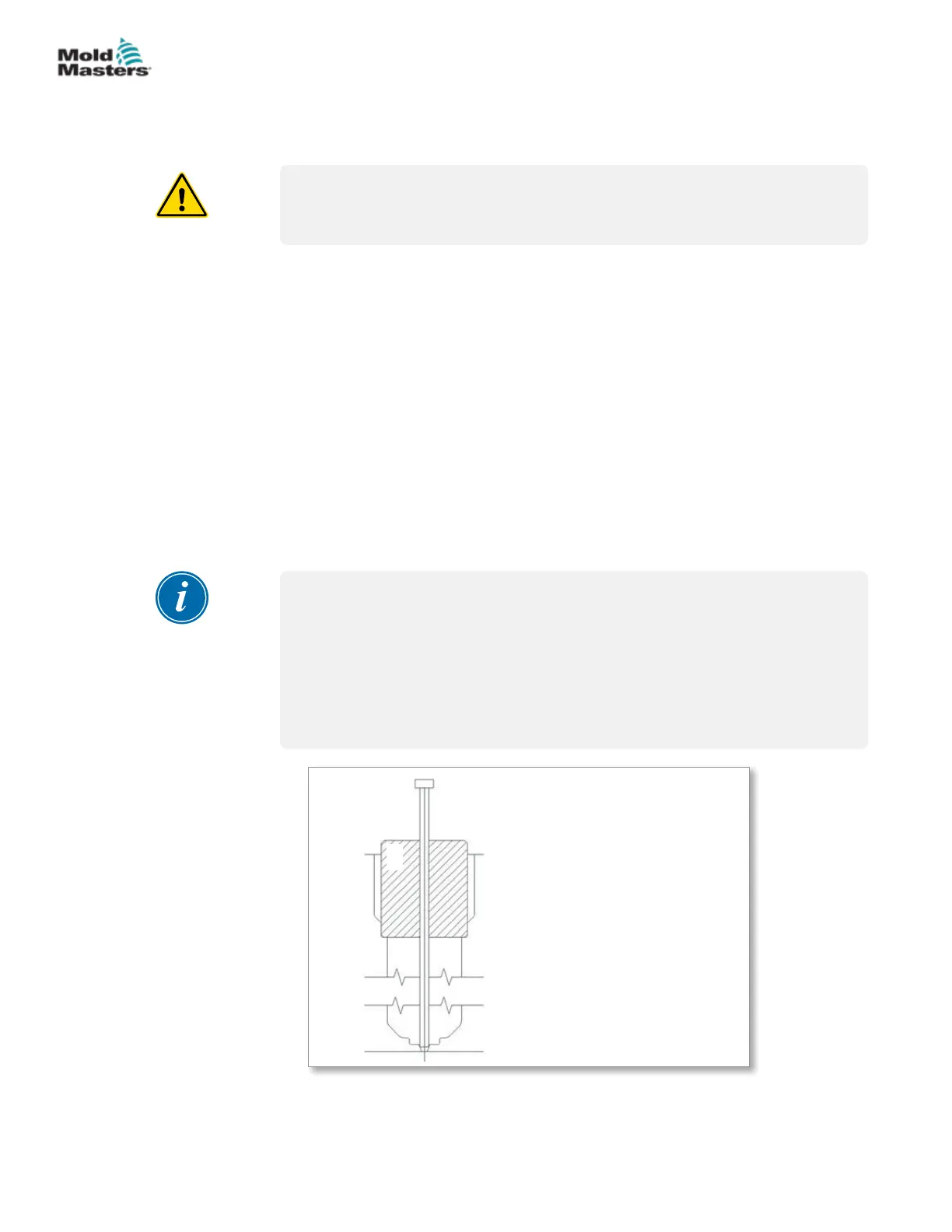
If the shut o between the valve pin and gate area is not satisfactory, lapping
of the valve pin into the gate will be required. A support bushing that ts into
the nozzle ange area should be manufactured with the pin diameter in the
center of the support bushing to properly align the pin with the gate area (see
below). Or use the nozzle well diameter of the cavity for the support bushing
as a lapping guide.
1. Install the machined bushing with the center hole matching the pin
diameter.
2. Insert the valve pin through the bushing.
3. Add 400 grit lapping paste to the tapered area of the pin and lap into the
gate. Verify the shut-o with die spotting blue compound.
4. Be sure to remove all lapping paste from the valve pin and cavity, before
continuing with actuator assembly.
NOTE
Do not permit the lapping paste to enter the valve bushing bore.
The Viton O-rings used for the valve actuators are rated for operation below
200°C (400°F).
Always turn ON the plate cooling prior to heating the Hot Runner system.
Refer to the warning if O-rings have been subjected to higher than rated
temperatures.
1. Nozzle ange bore
2. Machined bushing for center
alignment
3. Tapered / angled valve pin
4. Nozzle well bore
5. Cavity
1
2
3
4
5
Figure 10-14 Bushing for pin lapping
10-10
© 2020 Mold-Masters (2007) Limited. All Rights Reserved.
HYDRAULIC / PNEUMATIC ACTUATORS
Hot Runner User Manual