19.4.2 Melt-CUBE Design B: Maintenance Toolkit
Toolkit MCKITM10 has two components:
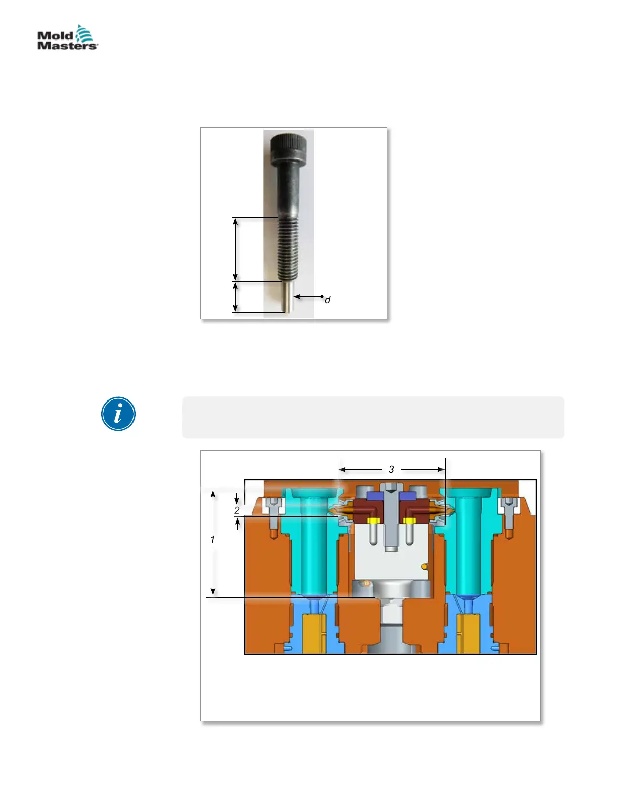
• M10-1.5 jack bolt (SHCSM10X50-A) — see Figure 19-7
• Needlenose pliers (COTS0254)
25mm
17mm
6mm (1/4”)
dowel
Figure 19-7 M10-1.5 jack bolt (SHCSM10X50-A)
19.4.3 Melt-CUBE Design B: Inspection
Inspect and document the critical dimensions for cavity cutout as shown in
Figure 19-8.
IMPORTANT
These dimensions must match the General Assembly drawing.
1
2
3
1. Distance from the bottom of the cavity plate to the top of the cavity
2. Gate cutout diameter
3. Distance between the cavities where the Melt-CUBE and the gate
seals are placed
19-20
© 2020 Mold-Masters (2007) Limited. All Rights Reserved.
MELT-CUBE SYSTEMS
Hot Runner User Manual