10.11 Proximity Sensor Installation for Hydraulic
Limit Switch Option
CAUTION
To avoid damage to the proximity switches during mounting, the default
torque value should not be exceeded. Reduce torque values by 30% at the
sensor’s face. M8 = 10 Nm (7 ft-Ib).
CAUTION
NOTE
The nominal sensing distance of the proximity sensor is 1.5 mm.
Refer to “10.12 Test the Proximity Sensor for Hydraulic Limit Switch Option”
on page 10-20.
1. Before assembling the sensor into bracket hole, ensure that the assembly
direction of the bracket part and cutout options are correct, based on
stroke and gate position. See “Figure 10-23 Single sensor / bracket
assembly” on page 10-18. Insert one proximity sensor into the metal
bracket hole. Lock the position of the proximity sensor with the lock nuts.
See “10.11.1 Cutout Options Based on Stroke” for examples.
2. Install the bracket assembly over the cylinder top and lock its position with
the socket head cap screw.
3. Adjust the sensor’s distance using lock nuts until the sensor detects the
trigger ring, after which the LED light will turn on.
4. Repeat steps 1-3 to install the other bracket assembly into the cylinder
top.
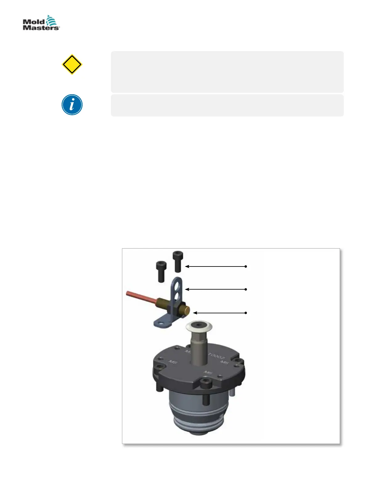
1. Socket head cap
screw
2. Sheet metal sensor
bracket
3. Proximity sensor with
lock nuts
2
1
3
Figure 10-23 Single sensor / bracket assembly
10-18
© 2020 Mold-Masters (2007) Limited. All Rights Reserved.
HYDRAULIC / PNEUMATIC ACTUATORS
Hot Runner User Manual