14.1 Mag-Pin Assembly (3D View)
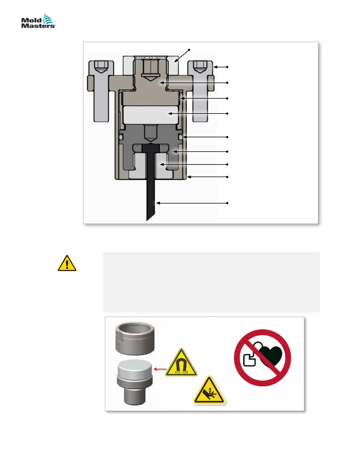
Figure 14-1 Mag-Pin assembly
1. NUTLM12F-01
(Locking nut)
2. SHCSM5X15
(Recommended screws for
attachment to synchro-plate)
3. MAGVPRTNR01
(Magnet retainer)
4. VPMAGHOLDER02
(Magnet holder)
5. VPMAGNET01
(Magnet)
6. HYORG018
(O-ring for dust protection)
7. MAGVPHLDR01
(Valve pin holder)
8. NUT0003
(Valve pin retaining nut)
9. VPMAGHOUSING02
(Main holder body)
10. VALVE PIN
(STD 2.5 or 3 mm)
14.2 Mag-Pin Safety
WARNING
-
STRONG MAGNETIC FIELD HAZARDS
Persons with pacemakers or other metallic, electronic, magnetic implants,
devices or objects shall not enter the magnetic eld area.
Do not keep any tools or metal objects in the magnetic eld area. Failure to
follow the instructions can cause injury to personnel and / or damage to the
parts.
Figure 14-2 Mag-Pin safety hazards
2
3
1
4
5
7
9
8
10
6
14-2
© 2020 Mold-Masters (2007) Limited. All Rights Reserved.
MAG-PIN OPTION
Hot Runner User Manual