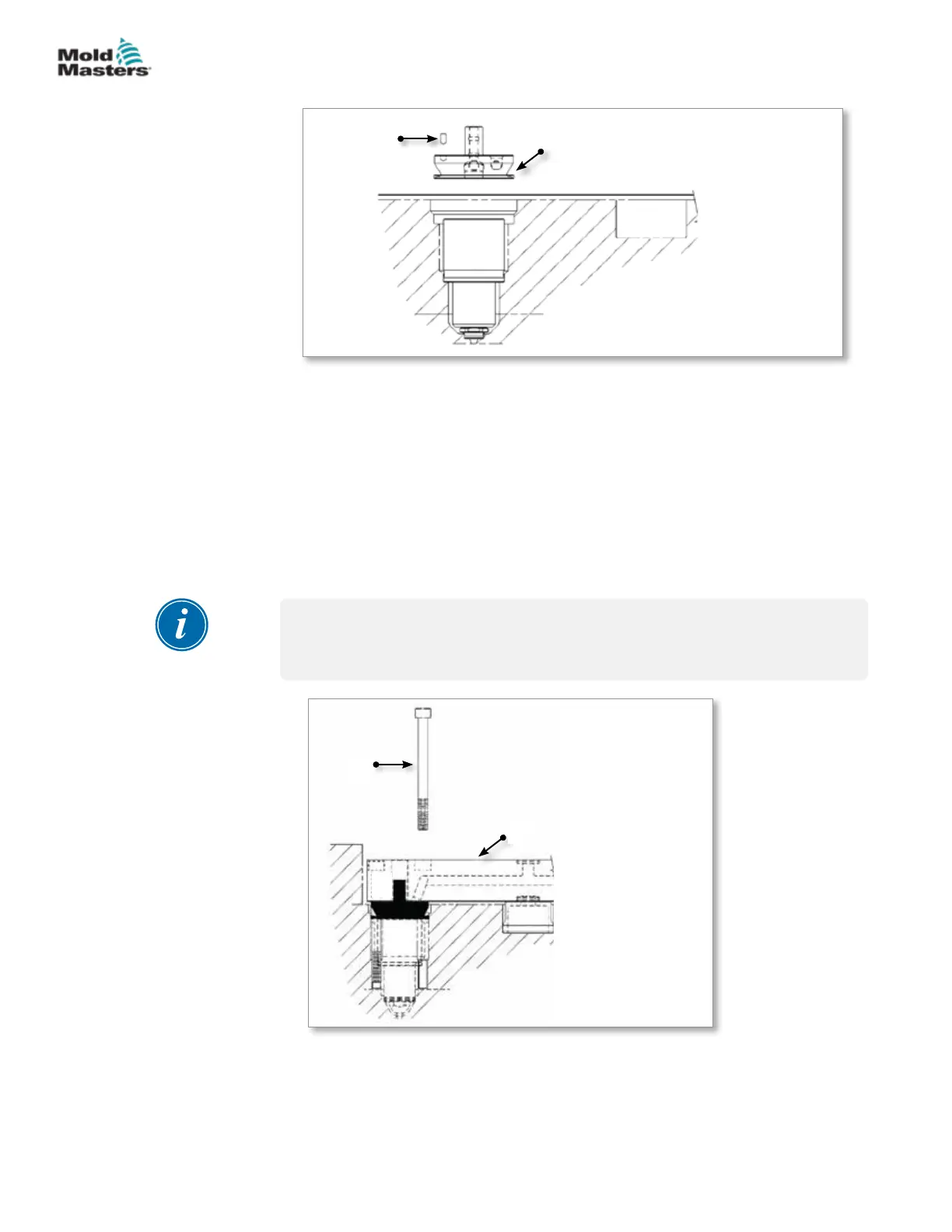
1. Locating dowel
2. Nozzle
3. Valve bushing
1
2
3
3.
Figure 5-17 Valve bushing - dowel pin installation
Apply anti-seize compound to the threads of each screw.
4. Make sure that the dowels are in correct position.
5. Lower the manifold into position.
6. Install screws through the manifold and into the manifold plate (the
mounting screw thread must start at the ange seal level). Refer to the
General Assembly drawings for correct screw size.
7. Torque screws to value indicated on the General Assembly drawings and
secure manifold to the manifold plate.
NOTE
On bridge manifold systems, main to submanifold screws should be torqued
1/3 higher than specied on General Assembly drawing.
1. Mounting screw
2. Manifold
3. Valve bushing
4. Nozzle
1
2
4
3
Figure 5-18 Valve bushing - screw installation
Valve Bushing Installation - continued
5-29ASSEMBLY
Hot Runner User Manual
© 2020 Mold-Masters (2007) Limited. All Rights Reserved.