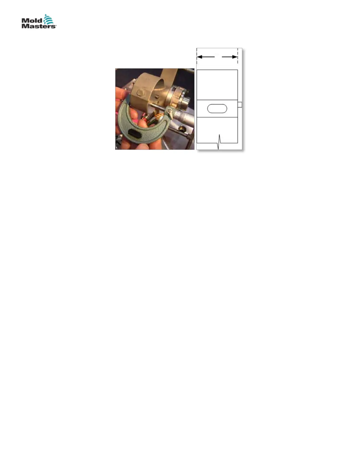
c) Measure the manifold thickness “c”.
c
Figure 5-29 Calculating manifold thickness“c”
2. Calculate Pressure Disk height “d” = a – b – c – air gap.
This is the value (“d”) that is required for correct assembly. Refer to the
General Assembly drawing for reference values, such as the air gap.
3. The actual height (thickness) of the supplied pressure disk “e” will be of a
value that is higher than the value “d”. Calculate the dierence, and then
divide by 2. This is the value that will need to be ground from each side of
the pressure disk.
Example Calculations:
Nozzle pocket depth “a”: 91.39 mm (3.60 in.)
Nozzle ange height “b”: 43.16 mm (1.70 in.)
Manifold thickness “c”: 43.16 mm (1.70 in.)
Air gap as noted on drawing: 0.05 mm (0.002 in.)
Pressure disk height “d”: 91.39 - 43.16 - 43.16 - 0.05 = 5.02 mm (0.20 in.)
Supplied pressure disk “e”: 5.10 mm (0.20 in.)
Dierence between supplied pressure disk “e” and required pressure disk “d”:
5.10 mm - 5.02 mm = 0.08 mm (0.003 in.)
Material to be removed from each side of the pressure disk:
0.08 mm ÷ 2 = 0.04 mm (0.002 in.)
Nozzle bores and pressure disks must be within tolerances specied in the
General Assembly drawing.
Pressure Disk: Final Grinding Required - continued
5-37ASSEMBLY
Hot Runner User Manual
© 2020 Mold-Masters (2007) Limited. All Rights Reserved.