2 Design
2 - 44
High-function General-purpose Inverter 3G3RX-V1 User’s Manual (I578-E1)
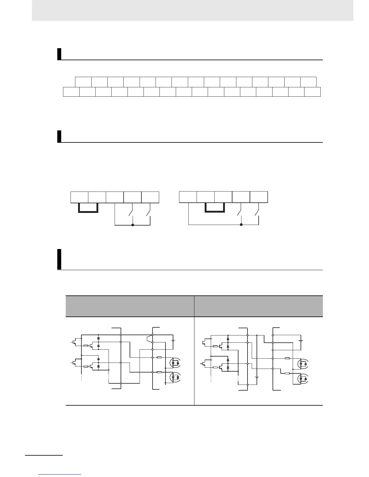
The arrangement of the control circuit terminal block is shown below.
By factory default, the terminal FW and the multi-function input terminal are set to sink logic (NPN).
To change the input control logic to source logic (PNP), remove the short-circuit bar between the
terminals P24 and PSC on the control circuit terminal block, and connect it between the terminals PSC
and SC.
Sink logic
Arrangement of Control Circuit Terminal
Changing Input Control Logic
Multi-function Input Terminals and Programmable Controller
Connection
When inverter’s internal interface power supply is
used
When external power supply is used
(Remove the short-circuit bar from the control
terminal block)