7 - 71
7 Detailed Functions
High-function General-purpose Inverter 3G3RX-V1 User’s Manual (I578-E1)
7-4 Detailed Functions (Group b)
7
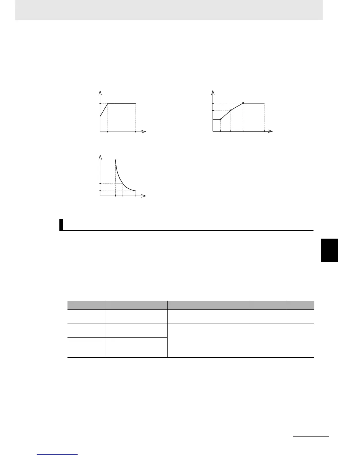
(Example) Examples of Free-Electronic Thermal Characteristics
• Start by setting the Free-electronic Thermal Frequency 3 and the Free-electronic Thermal
Current 3.
• The reduction factor for frequencies of 5 Hz or less is defined independent of that for the
free-electronic thermal function.
The actual reduction factor will be multiplied by the Free-electronic Thermal Current settings.
• The electronic thermal function can be to output an electronic thermal warning before the inverter
detects an overload.
This output not only allows the prior recognition of an overload condition, but also can be used as a
timing signal to improve that overloaded condition.
• In the Electronic Thermal Warning Level (C061), set the level at which a warning is output.
Set this value as a percentage of the integrated electronic thermal value. Take into consideration that
an overload error is detected when the integrated electronic thermal value reaches 100%.
• Set the Multi-function Output P1 to P5 Selection (C021 to C025) or the Multi-function Relay Output
(MA, MB) Function Selection (C026) to 13 (THM: Electronic thermal warning).
Electronic Thermal Warning Function
Parameter No. Function name Data Default data Unit
C061
Electronic Thermal
Warning Level
0. to 100. 80 %
C021 to C025
Multi-function Output P1
to P5 Selection
13: THM (Electronic thermal
warning)
––
C026
Multi-function Relay
Output (MA, MB) Function
Selection
Reduction
factor
x1.0
x0.8
0
540
Inverter output
frequency [Hz]
Output current
value [A]
b020
b018
b016
0
b015 b017 b019
A004/A204/A304
Max. frequency [Hz]
Trip time [s]
60
3.0
0 (x) (y) (z)
Motor current [A]
(Ratio to the rated current of the Inverter)
(Example) Output frequency = b017
(x): (b018/Rated current) ×109%
(y): (b018/Rated current) ×150%
(z): (b018/Rated current) ×200%