7 - 41
7 Detailed Functions
High-function General-purpose Inverter 3G3RX-V1 User’s Manual (I578-E1)
7-3 Basic Functions (Group A)
7
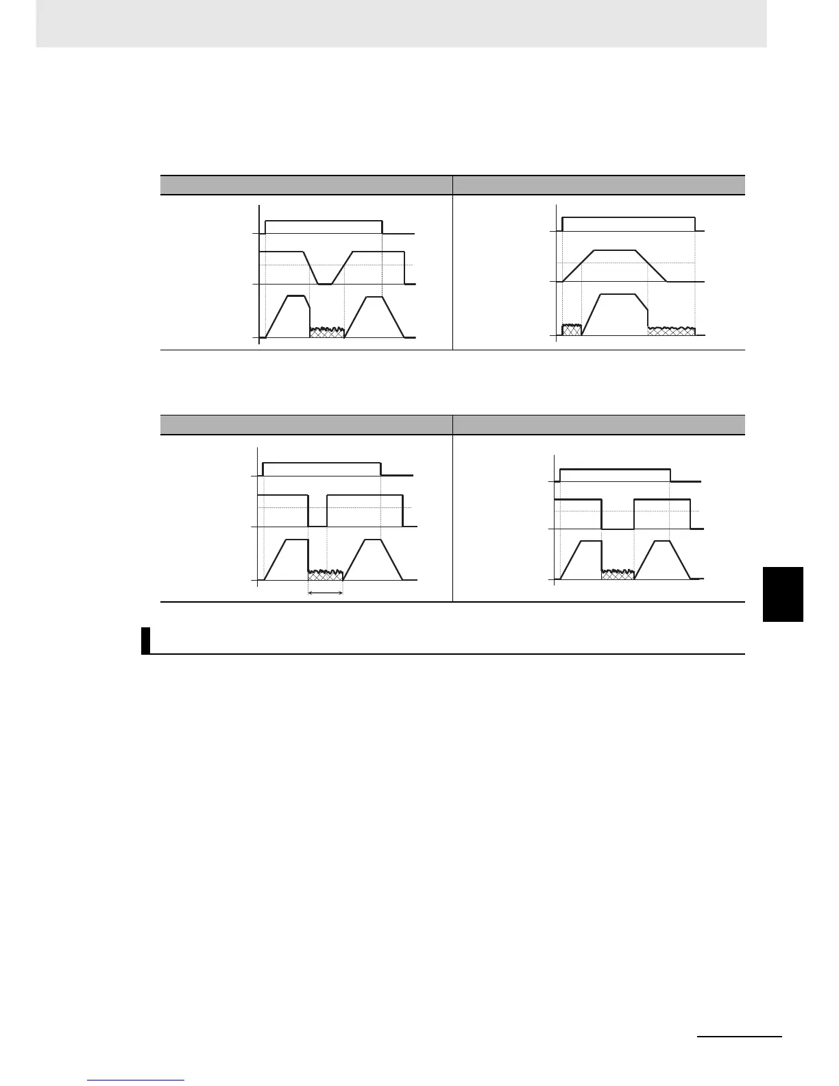
• If the reference frequency is 0 during startup via analog input etc., the inverter starts operating with
DC injection braking. (Example 7-b)
If the RUN command turns ON when the frequency reference is higher than the DC Injection Braking
Frequency (A052), the inverter starts operating with normal output. (Example 7-a)
• The inverter behaves differently when returning to normal operation depending on the value set in the
DC Injection Braking Edge/Level Selection (A056).
• Allocate one of the Multi-function Input S1 to S8 Selection (C001 to C008) to 07 (DB: External DC
injection braking).
• DC injection braking is applied by turning ON/OFF the DB terminal, independent of the DC Injection
Braking Selection (A051).
• In the DC Injection Braking Power (A054), set the strength or weakness of the DC injection braking
power.
• When the DC Injection Braking Delay Time (A053) is set, the inverter shuts off its output and remains
in a free-run state during the set time. After the expiration of the set time, the inverter starts DC
injection braking.
• Set the DC injection time via the DC Injection Braking Time (A055) or the DB terminal, while taking
into account the heat generation of the motor.
• Select the operation in the DC Injection Braking Edge/Level Selection (A056) and configure the
required settings according to your system.
(Example 7-a) (Example 7-b)
(a) Edge operation (A056= 00) (b) Level operation (A056= 01)
External DC Injection Braking
ON
RUN
command
A052
Frequency
reference
Output
frequency
ON
A052
RUN
command
Frequency
reference
Output
frequency
ON
A052
A055
RUN
command
Frequency
reference
Output
frequency
A052
ON
FW input
Frequency
reference
Output
frequency