6 Vector Control
6 - 18
High-function General-purpose Inverter 3G3RX-V1 User’s Manual (I578-E1)
Example
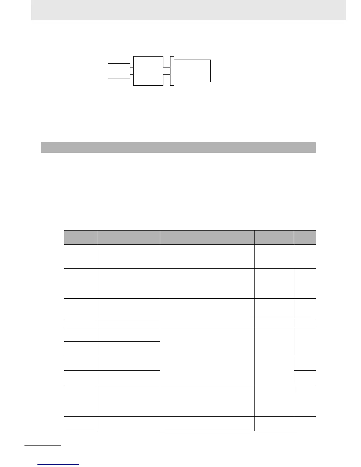
For a motor-to-encoder reduction ratio of 1 to 10, set the following parameters values.
• Number of Encoder Pulses (P011): 1,024
• Motor Gear Ratio Numerator (P028): 1
• Motor Gear Ratio Denominator (P029): 10
• Use this function to measure and automatically set the motor parameters required for the sensorless
vector control, 0-Hz sensorless vector control, or sensor vector control.
• To use the sensorless vector control, 0-Hz sensorless vector control, or sensor vector control
method, perform offline auto-tuning to measure the motor parameter values.
• If an Encoder disconnection (E60. / E70. ) or Overspeed (E61. /E71. ) error occurs, check the
encoder wiring and the parameter settings for the PG Board.
• Sensor vector control can be used only for the 1st control method.
• The measured motor parameter values will be set as 50-Hz data for one phase in 3-phase
Y-connection.
6-3-4 Auto-tuning of Motor Parameters
Parameter
No.
Function name Data Default data Unit
H001 Auto-tuning Selection
00: Disabled
01: Enabled (No motor rotation)
02: Enabled (Motor rotation)
00 –
H002
1st Motor Parameter
selection
00: Standard motor parameter
01: Auto-tuning
02: Auto-tuning (Online auto-tuning
enabled)
00 –
H003 1st Motor Capacity
0.1/0.2/0.4/0.55/0.75/1.1/1.5/2.2/3.0/3.7/
4.0/5.5/7.5/11.0/15.0/18.5/22/30/37/45/
55/75/90/110/132
Maximum
applicable
motor capacity
kW
H004 1st Motor Pole Number 2/4/6/8/10 4 pole
H030
1st Motor Parameter R1
(Auto-tuning Data)
0.001 to 9.999
10.00 to 65.53
Dependent on
motor capacity
Ω
H031
1st Motor Parameter R2
(Auto-tuning Data)
H032
1st Motor Parameter L
(Auto-tuning Data)
0.01 to 99.99
100.0 to 655.3
mH
H033
1st Motor Parameter lo
(Auto-tuning Data)
A
H034
1st Motor Parameter J
(Auto-tuning Data)
0.001 to 9.999
10.00 to 99.99
100.0 to 999.9
1000. to 9999.
kg/m
2
A003 1st Base Frequency
30. to 1st/2nd Maximum Frequency
(A004, A204)
60 Hz