1 Overview
1 - 24
High-function General-purpose Inverter 3G3RX-V1 User’s Manual (I578-E1)
1-5 Comparison with Previous Model
The following describes the changes and additions from the conventional 3G3RX Series.
Use this information when replacing the previous model.
The color scheme for Digital Operator keys was reviewed thoroughly based on a global concept that
“run- and start-related keys are green” and “stop-related keys are red.” As a result, the key colors were
changed as shown below.
The inverter operation and parameter initialization methods are simplified according to the 3G3MX2
Series.
For details, refer to 3-1-2 Key Operation Method on page 3-6.
Elimination of the top display layer (complete display of each function mode)
The top display layer in the operation ( ) was eliminated, although the concept of the function
modes remains as before.
Change of scroll behavior in each function mode
The parameter numbers loop in each function mode when scrolled.
Functions of Mode key and Enter key
The functions of the Mode key and the Enter key were changed as follows for consistency and
simplicity in operation.
• Mode key (or ESC key): Moves to the upper display layer (without entering the data).
• Enter key: Moves to the lower display layer, or enters the last data and returns to the upper display
layer.
Parameter Initialization method
Parameter initialization is performed by the parmeter setting without the complicated key operation
(simultaneous press of three keys).
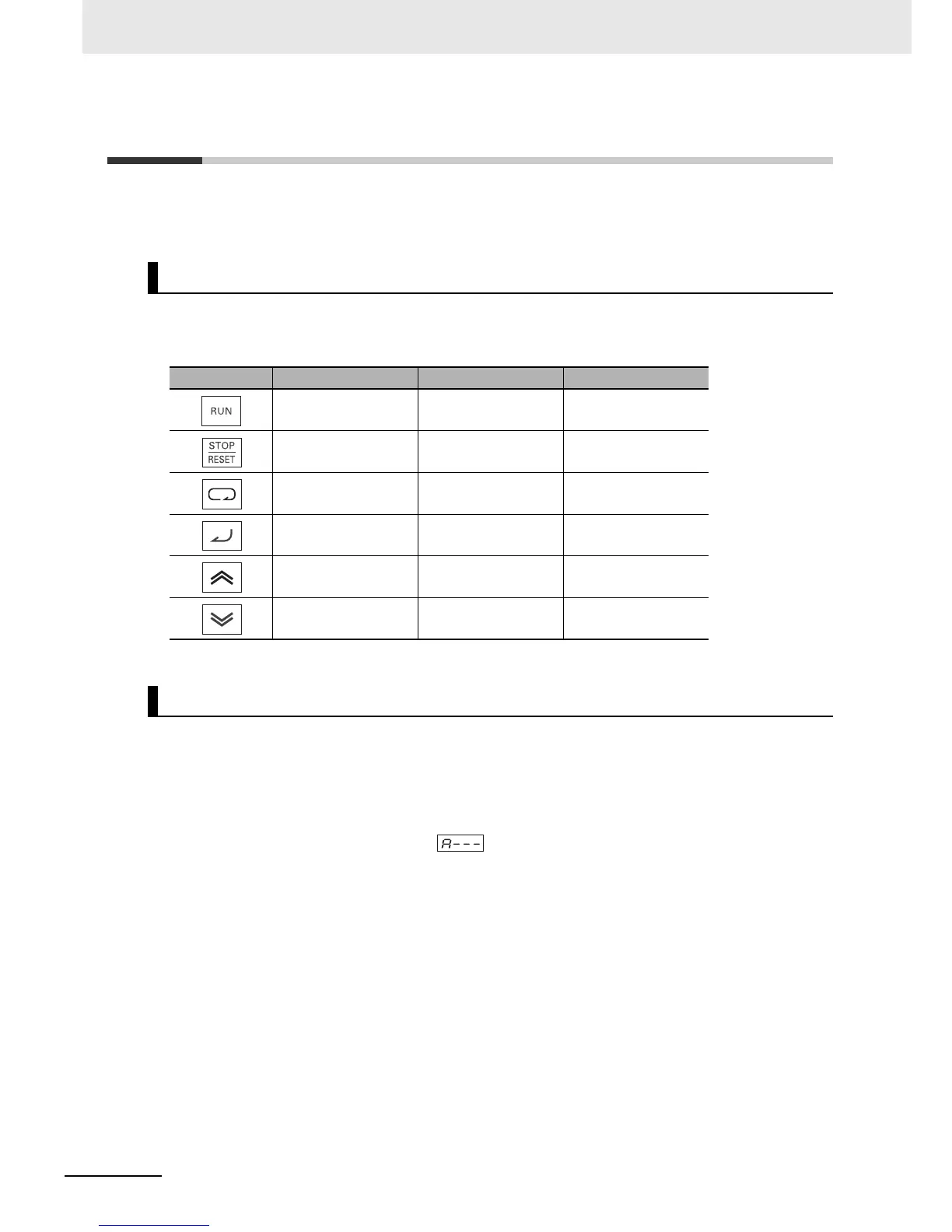
Change in Colors of Digital Operator Keys
Key Name Previous model 3G3RX Type V1
RUN key Gray Green
STOP/RESET key Yellow Red
Mode key Blue Blue (No change)
Enter key Yellow Yellow (No change)
Increment key Green Gray
Decrement key Green Gray
Changes in Operation and Initialization Methods from Previous Model