1 Overview
1 - 8
High-function General-purpose Inverter 3G3RX-V1 User’s Manual (I578-E1)
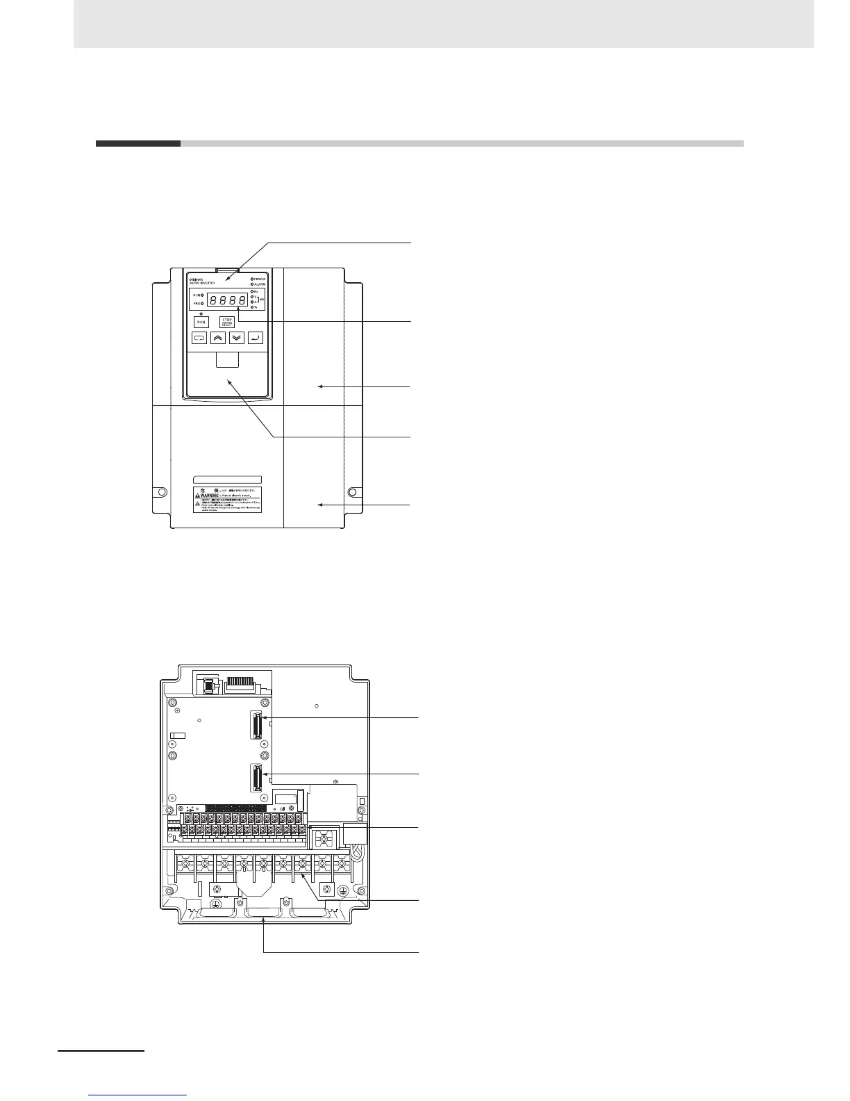
1-2 Appearance and Part Names
The following shows the front view when the product is unpacked (an example of
3G3RX-A2055-V1/A2075-V1/A2110-V1/A4055-V1/A4075-V1/A4110-V1).
Open the terminal block cover to wire the main circuit terminal block and the control circuit terminal
block.
Moreover, you can open the front cover to mount option boards.
Digital Operator
Data Display
Front Cover
Spacer Cover
Terminal Block Cover
Use this to set parameters, view various monitor data,
run/stop the inverter, etc.
This displays the frequency reference value, output
frequency, parameter set value, or other relevant data.
Remove this to mount option boards.
Remove this to mount optional units or 5-line LCD Digital
Operator.
Remove this when connecting cables to each terminal
block.
Connector for mounting option board 1
Connector for mounting option board 2
Use this to connect an option board.
Use this to connect an option board or
communications unit.
Control circuit terminal block
Use this to connect various digital/analog I/O signals
for inverter control.
Backing plate
Cut off the cutout portions of this plate to connect
power supply lines, signal lines, etc.
Main circuit terminal block
Use this to connect the inverter main power supply,
motor, braking resistor, and other devices.