2 - 11
2 Design
High-function General-purpose Inverter 3G3RX-V1 User’s Manual (I578-E1)
2-2 Removal of Each Part
2
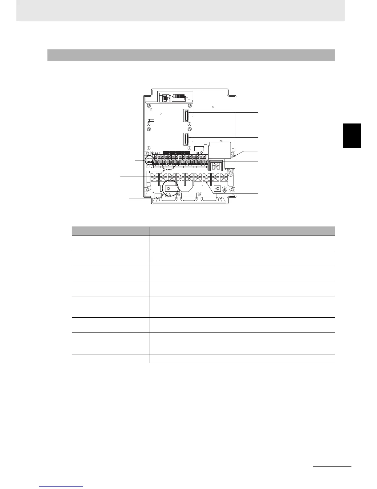
2-2-2 Terminal Blocks
Before wiring each terminal block, remove the terminal block cover and the backing plate.
2-2-2 Terminal Blocks
Name Description
Control circuit terminal block
The terminal block for connecting various digital/analog I/O devices used for
inverter control.
Main circuit terminal block
The terminal block for connecting the main power supply for the inverter,
outputs to the motor, Braking Resistor, etc.
Mounting position of option
board 1
The position where the option board (PG Board) is mounted.
Mounting position of option
board 2
The position where the option board (communications unit) is mounted.
Ground terminal with
short-circuit bar for switching
EMC filter function
The ground terminal with a short-circuit bar for switching the filter function for
compliance with the EMC Directives required by EC Directive.
RS485 communications
terminal block
The communications terminal for RS485 communications between the inverter
and external control equipment.
Charge indicator
Lights up even after power supply shutoff if the main circuit DC voltage
(between the P/+2 terminal and N/– terminal) is approximately 45 V or higher.
Make sure the charge indicator is not lit before wiring etc.
Slide switch SW1 Enables or disables the emergency shutoff function.
Mounting position of
option board 1
Mounting position of
option board 2
Control circuit terminal block
Main circuit terminal block
Charge indicator
RS485 communications
terminal block
Slide switch SW1
Ground terminal with
short-circuit bar for
switching EMC filter function