2 - 59
2 Design
High-function General-purpose Inverter 3G3RX-V1 User’s Manual (I578-E1)
2-3 Wiring
2
2-3-10 Conformance to EC Directives
Wiring for power supply
Keep the ground cable as short as possible.
Place the inverter and the noise filter on the same earth (ground) plate.
Always connect the power supply input terminals (R/L1, S/L2, T/L3) of the inverter to the power
supply via an EMC noise filter.
Keep the cable between the inverter and the EMC noise filter as short as possible (40 cm maximum).
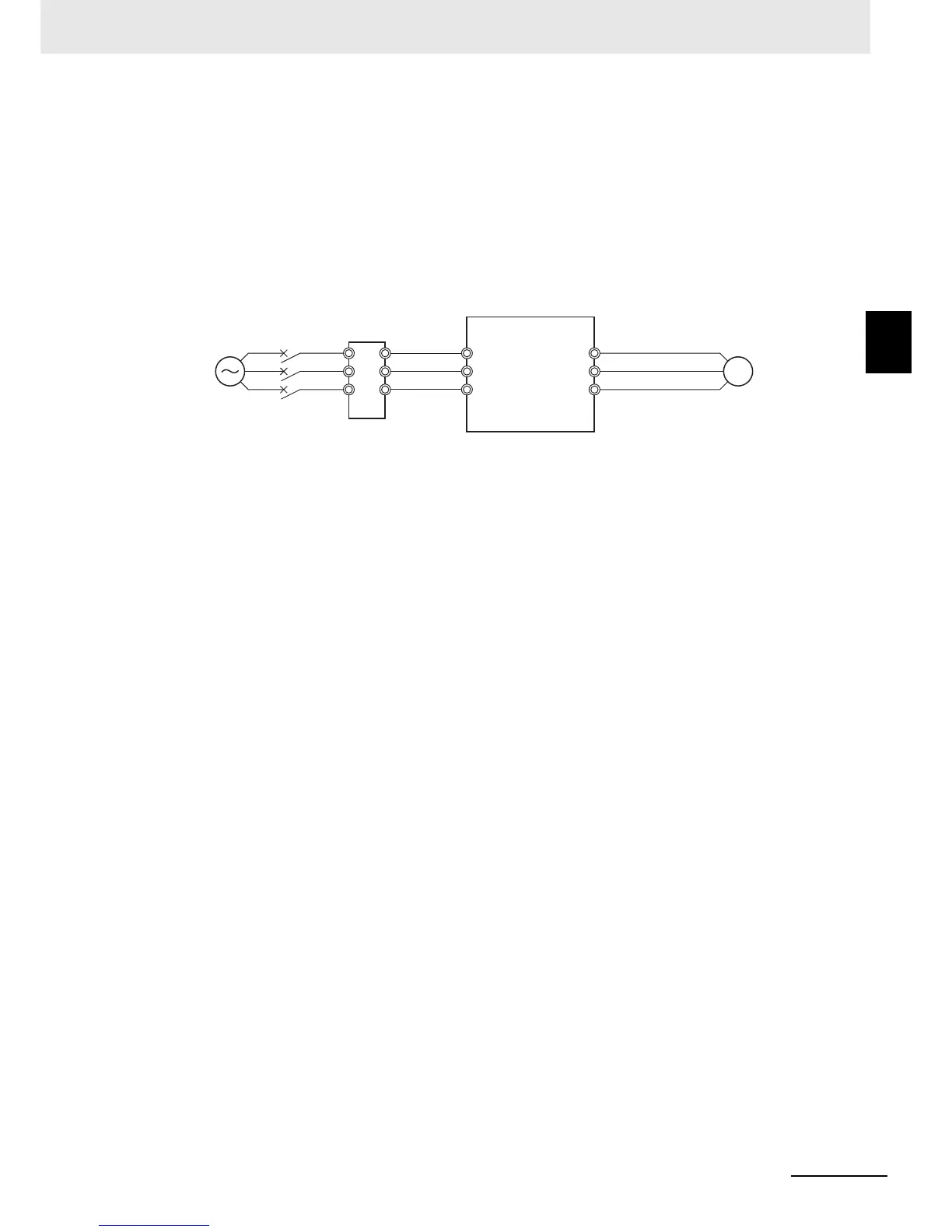
Connection Example
Wiring between inverter and motor
When connecting a motor to the inverter, be sure to use shield braided cables.
Keep the cables as short as possible.
Measures against noise
• For the power supply lines of the inverter, use a shield braided cable with a minimum cable length,
and connect via an EMC compliant input noise filter.
• Ground the cable shield.
• Keep the ground cable as short as possible. For 400-V class inverters, the ground terminal must
be connected to the neutral point of a power supply. Also ground the metal control panel as well
as the door simultaneously.
• Use shield braided cables also for connection between the inverter and the motor. Keep the cable
as short as possible at a length 20 m or less, with the cable shield grounded. Installing a clamp
filter near the inverter output terminals is an effective countermeasure.
• Connect the cable shield directly to an earth (ground) plate with a conductive cable clamp.
• With the motor frame grounded directly, connect the ground cable from the motor directly to an
EMC compliant input noise filter.
• For the control panel door, use a conductive gasket to improve the shielding effect.
• In the same control panel, do not install equipment that generates by design electromagnetic
waves, especially radio waves.
Low-voltage Directive
The 3G3RX-V1 Series Inverter complies with the EMC Directive EN61800-5-1 when installed with a
molded case circuit-breaker (MCCB) and wired according to the specified wiring method.
•
The 3G3RX-V1 Series Inverter is an open type device. Be sure to install it inside the control panel.
• The power supply and voltage (SELV) with reinforced or double insulation should be used for
wiring to the control circuit terminals.
• To satisfy requirements of the LVD (Low Voltage Directive), the inverter must be protected with a
molded case circuit breaker (MCCB) in case a short-circuiting accident occurs. Be sure to install a
molded case circuit breaker (MCCB) on the power supply side of the inverter.
• Use one molded case circuit breaker (MCCB) per inverter.
• Use the crimp terminal with an insulation sleeve to connect to the main circuit terminals.
• For 400-V class inverters, the ground terminal must be connected to the neutral point of a power
supply.