6 - 15
6 Vector Control
High-function General-purpose Inverter 3G3RX-V1 User’s Manual (I578-E1)
6-3 Sensor Vector Control
6
6-3-1 Sensor Vector Control Parameter Settings
6-3 Sensor Vector Control
Follow the steps below to set the sensor vector control function.
• Sensor vector control parameter settings
• PG Board settings
• Auto-tuning
• Adjustment
• Set the 1st Control Method (A044) to 05 (Sensor vector control).
• Set the 1st Motor Capacity (H003) and the 1st/ Motor Pole Number (H004) according to your motor.
• In the 1st Base Frequency (A003), set the rated frequency of the motor. In the Motor Rated Voltage
Selection (A082), set the rated voltage of the motor.
• Sensor vector control can be used only for the 1st control method.
• Sensor vector control cannot be used in the light load mode.
• In the V2 Control Mode Selection (P012), set the control method used for sensor vector control. You
can select speed control, position control, etc.
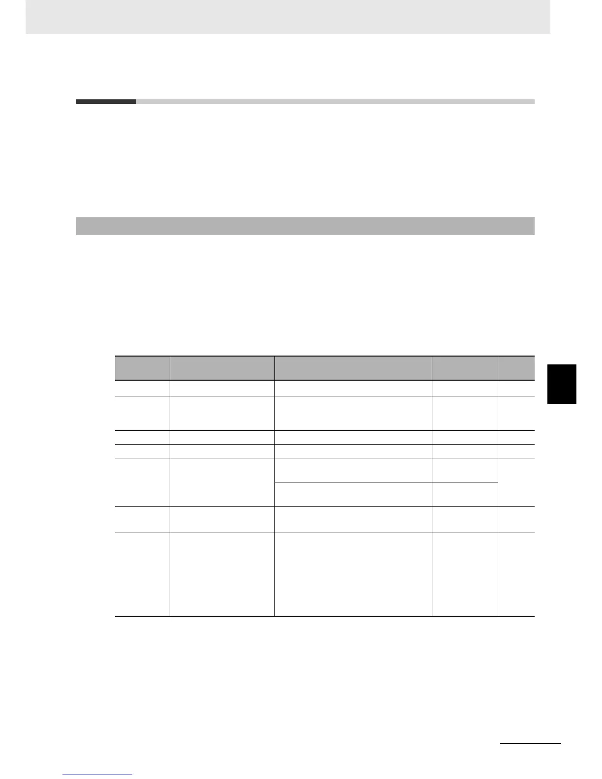
6-3-1 Sensor Vector Control Parameter Settings
Parameter
No.
Function name Data Default data Unit
A044 1st Control Method
05: Sensor vector control (V2)
*1
*1. Sensor vector control can be selected only for the 1st control method.
00 –
H003 1st Motor Capacity
0.1/0.2/0.4/0.55/0.75/1.1/1.5/2.2/3.0/3.7/
4.0/5.5/7.5/11.0/15.0/18.5/22/30/37/45/
55/75/90/110/132
Maximum
applicable
motor capacity
kW
H004 1st Motor Pole Number 2/4/6/8/10 4 pole
A003 1st Base Frequency 30. to 1st Maximum Frequency (A004) 60 Hz
A082
Motor Rated Voltage
Selection
200-V class: 200V/215V/220V/230V/
240 V
200
V
400-V class: 380 V/400 V/415 V/440 V/
460 V/480 V
400
b049
Heavy Load/Light Load
Selection
00: Heavy load mode (CT)
01: Light load mode (VT)
00 –
P012
V2 Control Mode
Selection
00: ASR (Speed control mode)
01: APR (Pulse train position control
mode)
02: APR2 (Absolute position control
mode)
03: HAPR (High-resolution absolute
position control mode)
00 –