2 Design
2 - 54
High-function General-purpose Inverter 3G3RX-V1 User’s Manual (I578-E1)
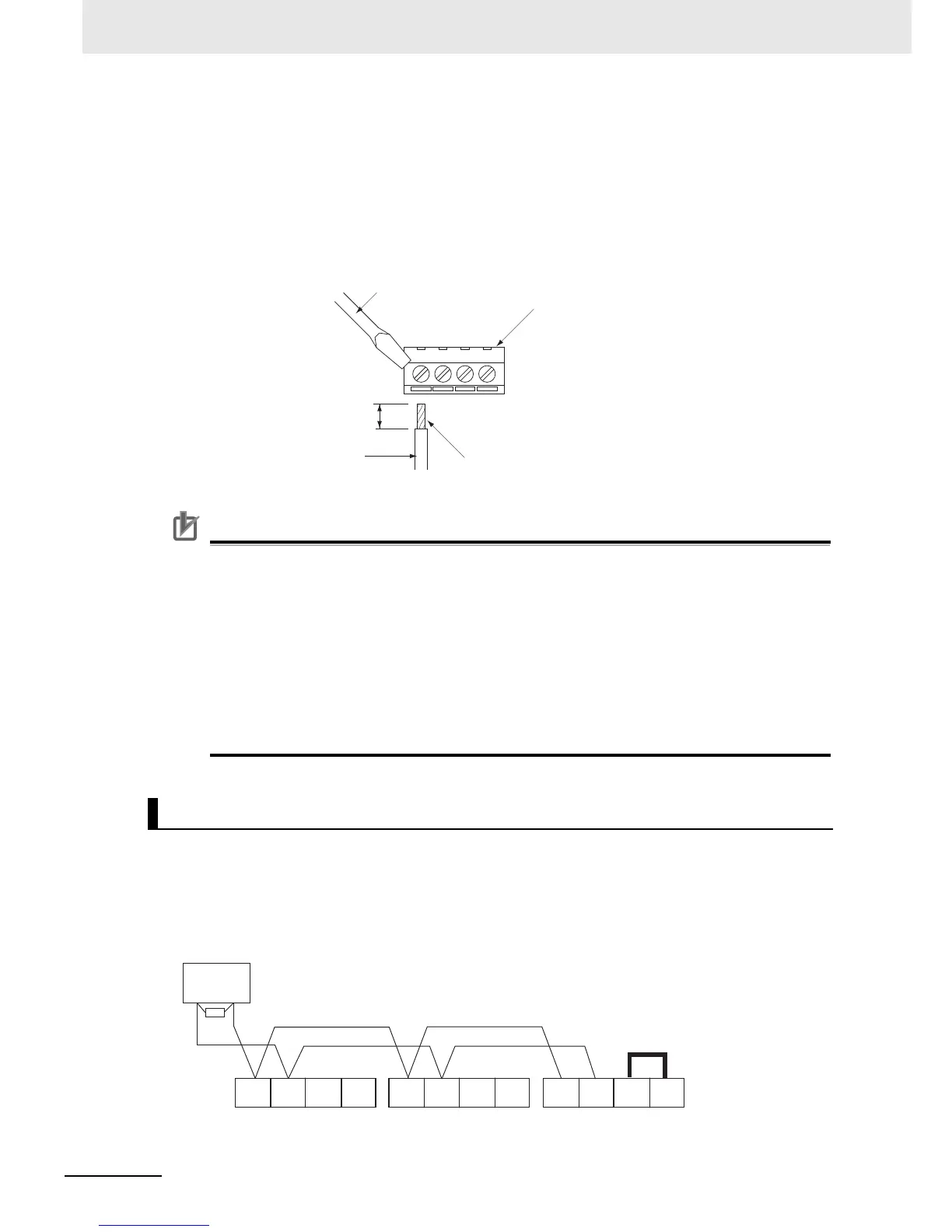
Wiring method
(1) Loosen the terminal screw with a thin flat-blade screwdriver.
(2) Insert the wire through the bottom of the terminal block.
(3) Tighten the terminal screw securely.
Be sure to tighten the terminal screws to the tightening torque specified in the table on the
previous page.
• Separate signal lines for control from the main circuit cable and other power supply/power
lines when wiring.
• Do not solder the wire ends. Doing so may result in a contact failure.
• When pin terminals are not used, the wire strip length must be approximately 5.0 mm.
• Connect the shielded cable to the terminal FC (frequency reference common) of the
3G3RX-V1 Series . Do not connect it to the controller.
• Insulate the cable shields with tape or some other means to prevent them from contact with
other signal lines or equipment.
• Tightening the screws to an excessive tightening torque may result in damage to the terminals.
Tightening them with a weak torque may also cause a malfunction or short-circuit.
Connect each inverter in series as shown below.
Because a terminating resistor must be installed at each end of communications wiring, enable the
terminating resistor only for the terminal inverter.
Use the terminating resistor even if you have only one inverter connected.
For this inverter, shorting the terminals RP and RS– enables the built-in terminating resistor (100 Ω).
Terminating Resistor Installation
Thin flat-blade screwdriver
Terminal block
Wire with crimp pin terminal,
or non-soldered wire
Cable
Strip length
Approx. 5.0 mm
(Without pin terminal)