2 - 43
2 Design
High-function General-purpose Inverter 3G3RX-V1 User’s Manual (I578-E1)
2-3 Wiring
2
2-3-5 Wiring for Control Circuit Terminals
• The terminals FC and SC are insulated from each other via the input and output signal common
terminals.
Do not short-circuit or ground these common terminals.
Do not ground these common terminals via external equipment.
When finished wiring, check the external equipment ground conditions.
• For wiring to the control circuit terminals, use twisted-pair shielded cables (recommended diameter:
0.75 mm
2
). Connect the sheathed shielded cable to each common terminal.
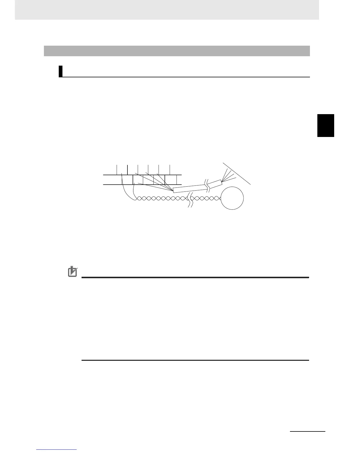
• Twist a cable connected to the terminal TH (thermistor input) with a cable of the terminal SC
individually, and separate them from other SC common cables. Since the current flowing through the
thermistor is weak, separate the thermistor cable from main circuit wiring (power lines). The
thermistor connection cable should be 20 m or shorter.
• To use a relay for a multi-function output terminal, connect a surge-absorbing diode in parallel with
the coil.
• The control circuit terminal block has two rows of terminals. Start wiring from the lower terminals.
Wiring from the upper terminals makes it difficult to wire the lower terminals.
• Wiring the I/O signal lines for more than one inverter results in creating a sneak path in the
circuit. Connect a diode for sneak current prevention. For wiring instructions, refer to
Precaution for Wiring Control Circuit Terminals on page 2-47.
• The control circuit connection cables should be 20 m or shorter.
• Separate the cables for control circuit terminal connection from the main circuit cable (power
lines) and the relay control circuit cable. If you cannot avoid crossing cables each other, try to
keep them at right angles to each other. Not doing so may result in the inverter malfunction.
Separate signal lines from power supply lines when wiring.
• Do not short-circuit the analog power supply terminals FS and FC and/or the interface power
supply terminals P24 and SC. Doing so may result in failure of the inverter.
• After wiring, lightly pull the wire to confirm that it is connected properly.
2-3-5 Wiring for Control Circuit Terminals
Wiring for Control Circuit Terminals