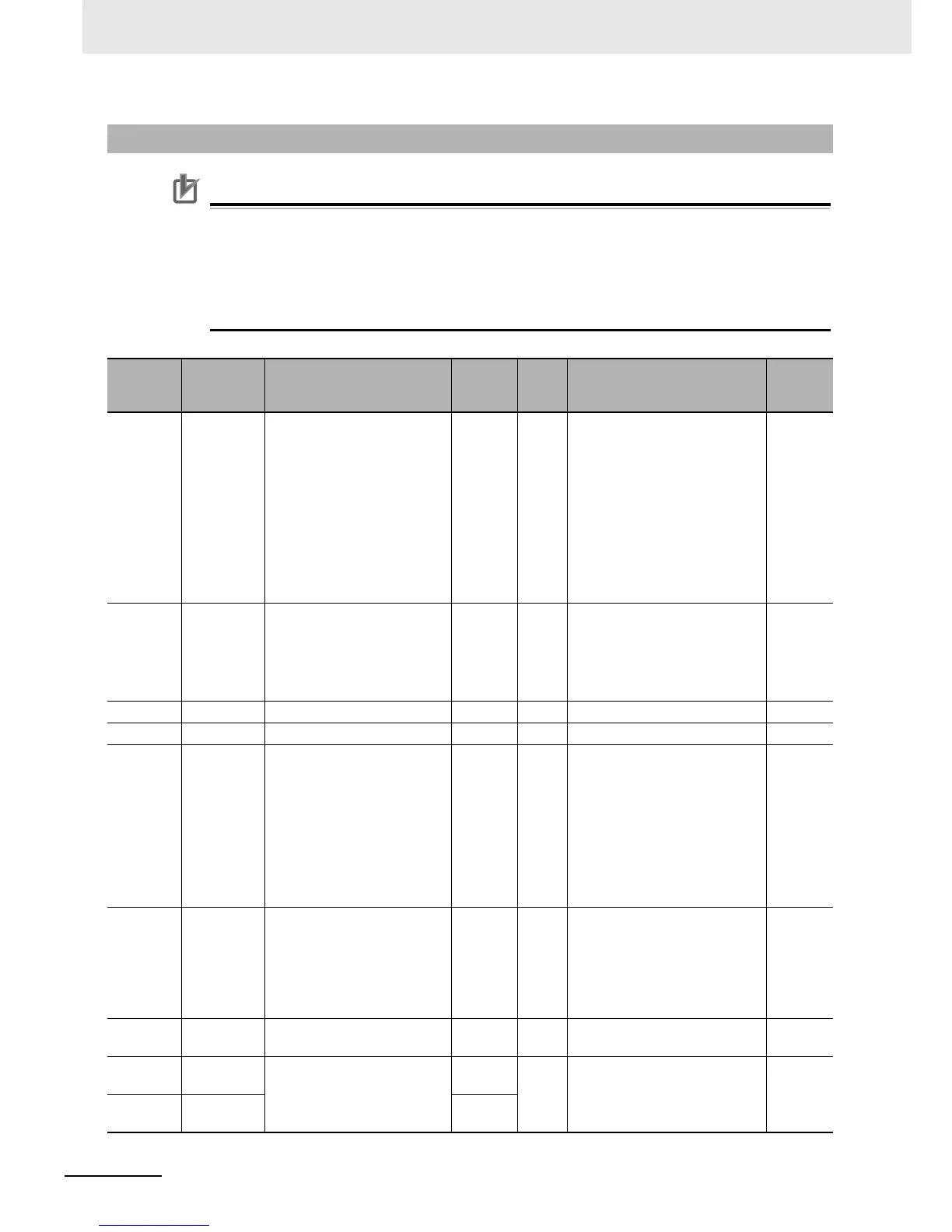
• The “Register No.” in the table header shows the resister number used inside the inverter.
Use this register number when setting communications or other options for the inverter.
• The “Modbus register spec. No.” in the table header shows the resister number used to
actually specify the resister in the Modbus communication process.
This resister number is 1 less than the inverter “Register No.” according to the Modbus
communication specifications.
8-5-4 Group A/b/C/H/P Register List
Register
No.
Modbus
register
spec. No.
Function name
Parameter
No.
R/W Monitor or setting data
Resolution
1201 hex 1200 hex
Frequency Reference
Selection
A001 R/W
0: Digital Operator (Volume
adjuster)
1: Control Circuit Terminal Block
2: Digital Operator (F001)
3: Modbus communication
4: Option 1
5: Option 2
6: Pulse train frequency
7: DriveProgramming
10: Operation function output
–
1202 hex 1201 hex RUN Command Selection A002 R/W
1: Control Circuit Terminal Block
2: Digital Operator (F001)
3:
Modbus communication
4: Option 1
5: Option 2
–
1203 hex 1202 hex 1st Base Frequency A003 R/W 30 to Max. frequency 1 [Hz]
1204 hex 1203 hex 1st Maximum Frequency A004 R/W 30 to 400 1 [Hz]
1205 hex 1204 hex FV/FI Selection A005 R/W
0: Switching between FV
(voltage) and FI (current)
1:
Switching between FV and FE
2:
Switching between FV and
volume adjuster via terminal AT
3:
Switching between FI and
volume adjuster via terminal AT
4:
Switching between FE and
volume adjuster via terminal AT
–
1206 hex 1205 hex FE Selection A006 R/W
0: FE only
1: FV/FI auxiliary frequency
reference (Not reversible)
2: FV/FI auxiliary frequency
reference (Reversible)
3: FE disabled
–
1207 to
120A hex
– Not used – – – –
120B hex 120A hex
FV Start Frequency
A011
(HIGH)
R/W 0 to 40000 0.01 [Hz]
120C hex 120B hex
A011
(LOW)