5 Basic Settings
5 - 62
High-function General-purpose Inverter 3G3RX-V1 User’s Manual (I578-E1)
• If an overcurrent, overvoltage, or some other error occurs, the inverter shuts off its output and
generates an alarm signal. This is called a “trip.”
• A trip state can be cancelled by resetting the inverter, by which the alarm signal also turns OFF. To
reset the inverter, press the STOP/RESET key on the Digital Operator or turn ON the reset terminal.
However, you may not be able to reset some trip factors by using these methods. In such cases, cycle
the power supply.
• Allocate one of the Multi-function Output P1 to P5 Selection (C021 to C025) or the Multi-function
Relay Output (MA, MB) Function Selection (C026) to 05 (AL). By default, the Multi-function Relay
Output (MA, MB) Function Selection (C026) is set to 05 (AL: Alarm signal).
The alarm signal will be output as shown below. You can change whether the inverter outputs an alarm
when it recognizes the power supply OFF status by using the combination of the Multi-function Output
P1 to P5 Operation Selection and Multi-function Relay Output (MA, MB) Operation Selection (C031 to
C036).
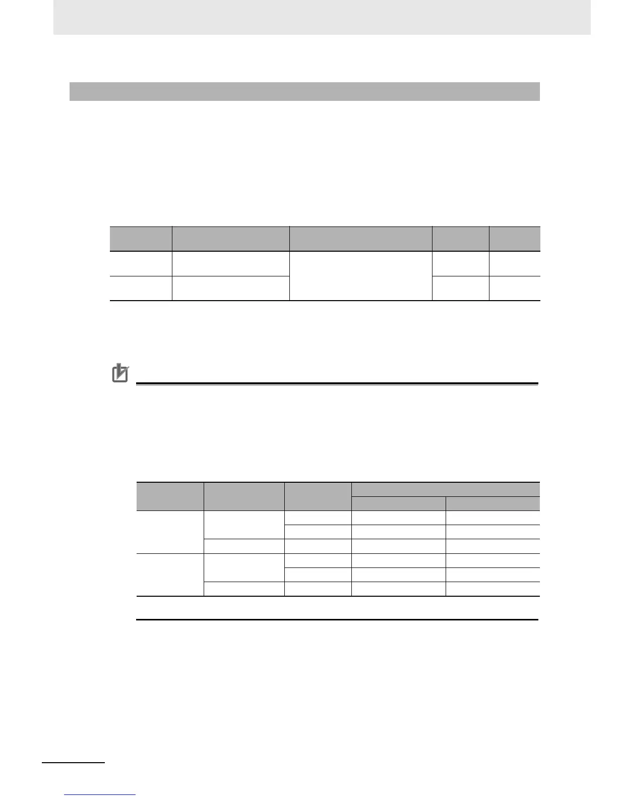
The relay output terminals are allocated to 05 (AL: Alarm output) by default. However, the relay
output status of the inverter when the input power supply is OFF is different from the previous
model (3G3V Series).
The table below shows the relationship between the relay output status when the inverter input
power supply is ON/OFF and the Multi-function Relay Output (MA, MB) Operation Selection
(C036) setting. Select the parameter setting appropriate to the sequence of your inverter
according to this table.
Note Set C036 to 00 to have the same relay output status as with the previous model (3G3V Series).
5-10-6 Alarm Signal (AL)
Parameter
No.
Function name Data Default data Unit
C021 to C025
Multi-function Output P1 to
P5 Selection
05: AL (Alarm signal)
––
C026
Multi-function Relay Output
(MA,MB) Function Selection
05 –
Setting in
C036
Input power
supply
Inverter status
Relay output status
Between MA and MC Between MB and MC
00 ON Normal Open Closed
Alarm output Closed Open
OFF – Open Closed
01
(Default data)
ON Normal Closed Open
Alarm output Open Closed
OFF – Open Closed