7 Detailed Functions
7 - 50
High-function General-purpose Inverter 3G3RX-V1 User’s Manual (I578-E1)
If PID control does not provide a stable response, adjust the appropriate gain setting according to the
table below.
• You can set the PID Deviation Excessive Level (C044) for PID control. This enables the inverter to
output a control signal from the multi-function output terminal to which the function is allocated when
the deviation reaches the value set in C044.
• The setting range for C044 is 0 to 100. Set this with the maximum target value defined as 100%.
• Set the Multi-function Output P1 to P5 Selection (C021 to C025) or the Multi-function Relay Output
(MA, MB) Function Selection (C026) to 04 (OD).
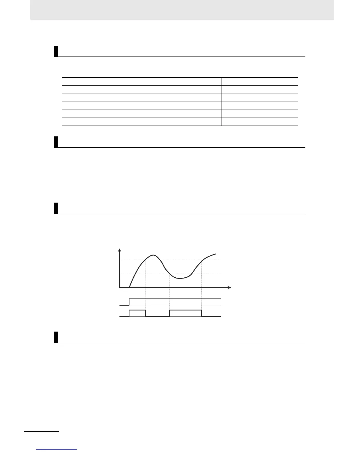
• The inverter can be configured to output a control signal from the multi-function output terminal to
which the function is allocated when the PID feedback value falls out of the setting range.
• Allocate one of the Multi-function Output P1 to P5 Selection (C021 to C025) or the Multi-function
Relay Output (MA, MB) Function Selection (C026) to 31 (FBV).
• Use this parameter to monitor the PID feedback value.
• The monitor value is displayed as a product of the feedback value and the PID Scale (A075).
PID Feedback Value Monitor (d004) = Feedback value [%] x PID Scale (A075)
PID Gain Adjustment
Changes in target value are not reflected quickly on feedback value. Increase PID P Gain (A072).
Changes are reflected quickly on feedback value, but not stable. Decrease PID P Gain (A072).
Target and feedback values do not match quickly. Decrease PID I Gain (A073).
Feedback value fluctuates unstably. Increase PID I Gain (A073).
Increasing PID P Gain does not improve response speed. Increase PID D Gain (A074).
Increasing PID P Gain results in fluctuating and unstable feedback value. Decrease PID D Gain (A074).
PID Deviation Excessive Level Detection (OD)
Feedback Comparison Signal
PID Feedback Value Monitor (d004)
PID feedback
FW input
ON
OFF
FBV
output
ON
OFF
Time
C052 (OFF level)
C053 (ON level)