4 Parameter List
4 - 2
High-function General-purpose Inverter 3G3RX-V1 User’s Manual (I578-E1)
4-1 Monitor Mode
The inverter by default displays the content of the parameter d001at power-on. To monitor the desired
parameter, change the setting in the Initial Screen Selection (b038).
4-1-1 Group d
Parameter
No.
Function name Monitor or data range
Default
data
Changes during
operation
Unit Page
Normal
b031 = 10
d001 Output Frequency
Monitor
0.00 to 99.99
100.0 to 400.0
– Enabled Enabled Hz 7-2
d002 Output Current
Monitor
0.0 to 999.9
1000. to 9999.
– ––A7-2
d003 RUN Direction
Monitor
F: Forward
o: Stop
r: Reverse
– –––7-2
d004 PID Feedback
Value Monitor
0.00 to 99.99
100.0 to 999.9
1000. to 9999.
1000 to 9999
(10000 to 99990)
Γ100 to Γ999
(100000 to 999000)
(Enabled when the PID function is
selected)
– –––7-3
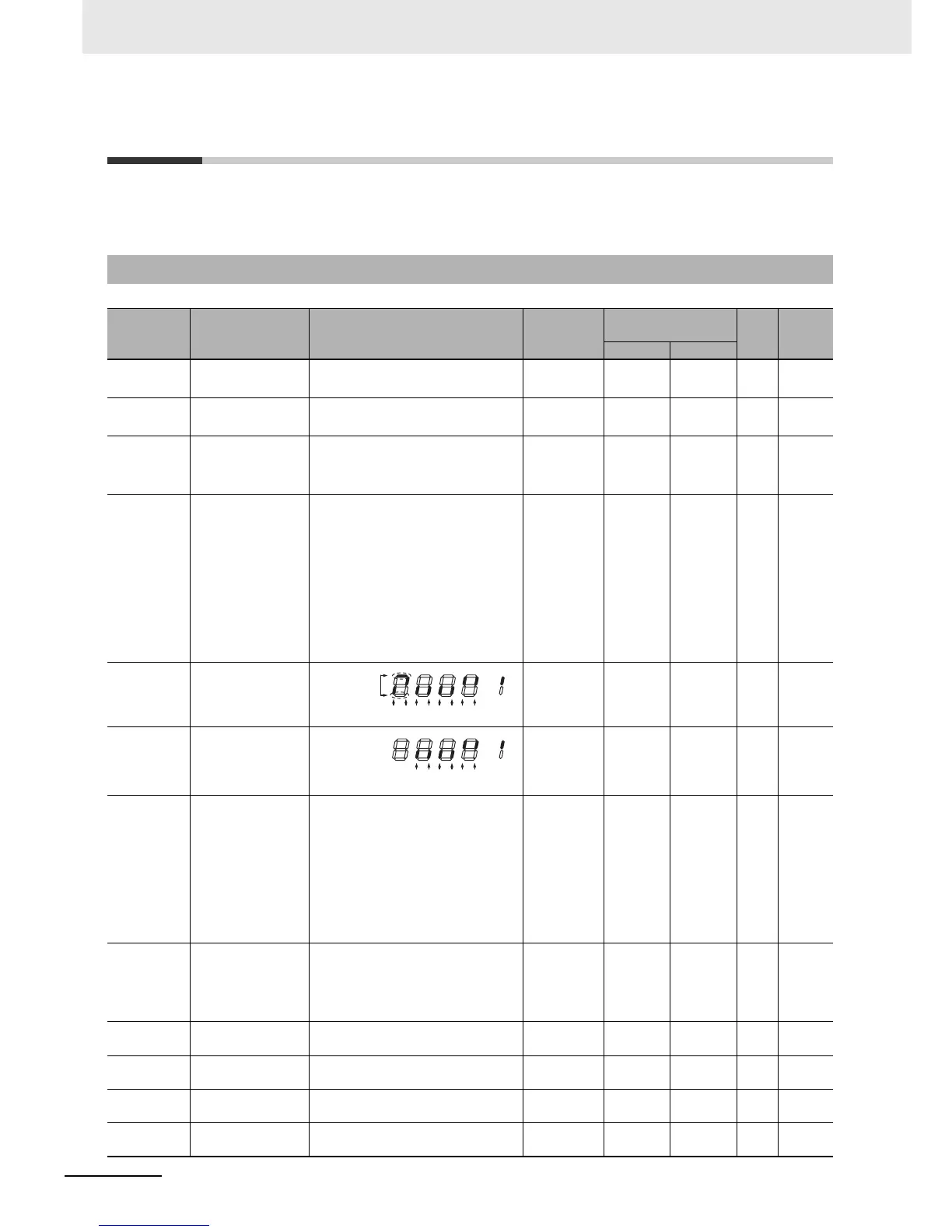
d005 Multi-function
Input Monitor
– –––7-3
d006 Multi-function
Output Monitor
– –––7-4
d007 Output Frequency
Monitor
(After Conversion)
0.00 to 99.99
100.0 to 999.9
1000. to 9999.
1000 to 3996
(10000 to 39960)
[Output Frequency (d001) x
Frequency Conversion Factor
(b086)]
– Enabled Enabled – 7-4
d008 Real Frequency
Monitor
0.00 to 99.99 (Forward)
100.0 to 400.0 (Forward)
–99.9 to –00.0 (Reverse)
–400. to –100. (Reverse)
– ––Hz7-5
d009 Torque Reference
Monitor
–200. to 200. – – – % 7-5
d010 Torque Bias
Monitor
–200. to 200. – – – % 7-5
d012 Output Torque
Monitor
–200. to 200. – – – % 7-6
d013 Output Voltage
Monitor
0.0 to 600.0 – – – V 7-6