6 Vector Control
6 - 34
High-function General-purpose Inverter 3G3RX-V1 User’s Manual (I578-E1)
6-6 Pulse Train Position Control Mode
• To use this function, set the 1st Control Method (A044) to 05 (Sensor vector control) and the V2
Control Mode Selection (P012) to 01 (Pulse train position control).
• Select the input mode for the pulse train position command in the Pulse Train Input Selection (P013).
• Set the positioning completion signal that determines the completion of position control.
Set the Multi-function Output P1 to P5 Selection (C021 to C025) or the Multi-function Relay Output
(MA, MB) Function Selection (C026) to 23 (POK: Position ready).
The position completion signal will be output when the current position reaches the target position
range set in the Positioning Completion Range Setting (P017). In the Positioning Completion Delay
Time Setting (P018), set the time until the signal is stabilized depending on your application.
6-6-1 Pulse Train Position Control Mode Settings
Under sensor vector control, select the heavy load mode (b049 = 00).
Sensor vector control can be selected only for the 1st control.
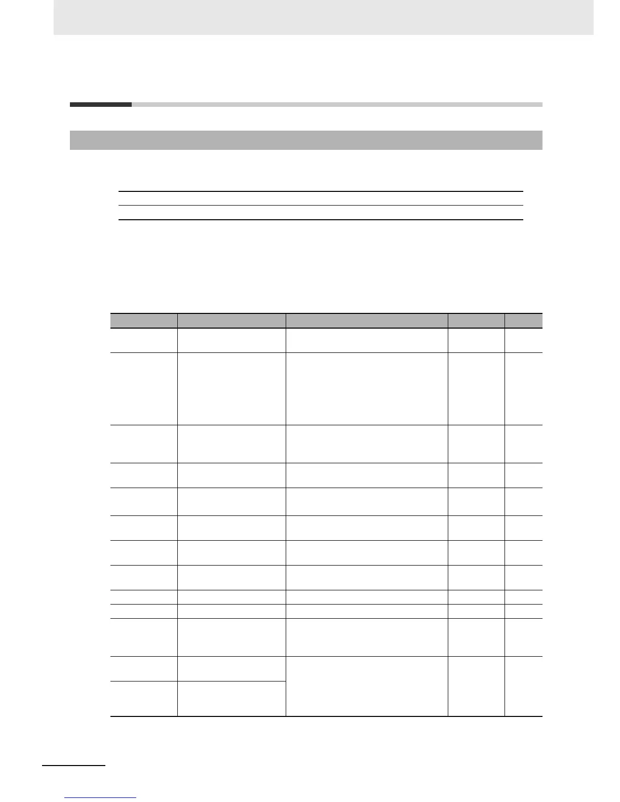
Parameter No. Function name Data Default data Unit
P012
V2 Control Mode
Selection
01: APR (Pulse train position control
mode)
00 –
P013
Pulse Train Input
Selection
00: Mode 0 (90°phase difference pulse
train)
01: Mode 1 ( Forward/Reverse command
+ pulse train)
02: Mode 2 (Forward/pulse train +
Reverse pulse train)
00 –
P017
Positioning Completion
Range Setting
0. to 9999., 1000 (10000):
Set as a value equivalent to encoder
resolution x4.
5. pulse
P018
Positioning Completion
Delay Time Setting
0.00 to 9.99 0.00 s
P019
Electronic Gear Position
Selection
00: FB (Position feedback side)
01: REF (Position command side)
00 –
P020
Electronic Gear Ratio
Numerator
1. to 9999. 1. –
P021
Electronic Gear Ratio
Denominator
1. to 9999. 1. –
P022
Position Control
Feedforward Gain
0.00 to 99.99, 100.0 to 655.3 0.00 –
P023 Position Loop Gain 0.00 to 99.99, 100.0 0.50 rad/s
P024 Position Bias Amount –204 (–2048), –999. to 2048. 0. –
C001 to C008
Multi-function Input S1 to
S8 Selection
47: PCLR (Position deviation clear)
48: STAT (Pulse train position command
input permission)
––
C021 to C025
Multi-function Output P1
to P5 Selection
23: POK (Position ready) – –
C026
Multi-function Relay
Output (MA, MB) Function
Selection