8 - 27
8 Communications Functions
High-function General-purpose Inverter 3G3RX-V1 User’s Manual (I578-E1)
8-5 Modbus Communication Register Number List
8
8-5-2 Monitor Function/Enter Command
Register List
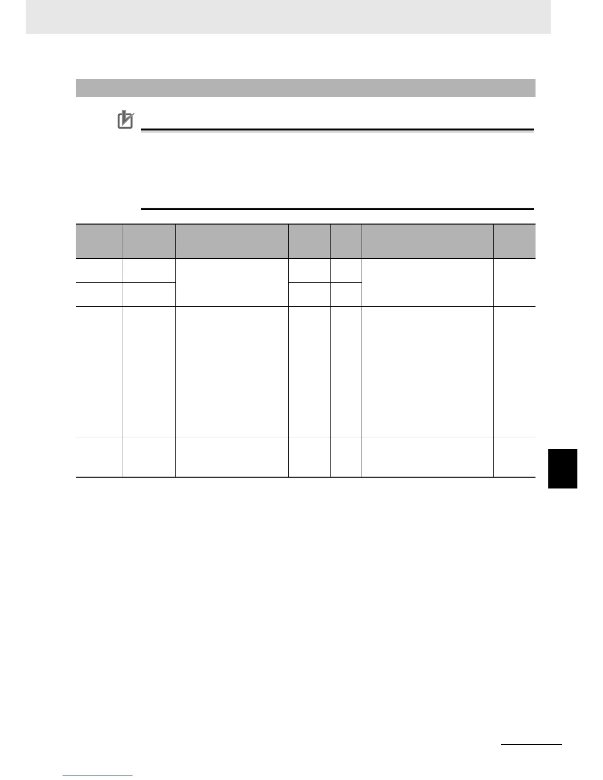
• The “Register No.” in the table header shows the resister number used inside the inverter.
Use this resister number when setting communications or other options for the inverter.
• The “Modbus register spec. No.” in the table header shows the resister number used to
actually specify the resister in the Modbus communication process.
This resister number is 1 less than the inverter “Register No.” according to the Modbus
communication specifications.
Note 1 The inverter’s rated current is 1,000.
2 When the set value is 10,000 (100.0 s) or more, the value in the second decimal place is ignored.
8-5-2 Monitor Function/Enter Command Register List
Register
No.
Modbus
register
spec. No.
Function name
Parameter
No.
R/W Monitor or setting data
Resolution
0001 hex 0000 hex
Output Frequency
Setting/Monitor
F001
(HIGH)
R/W
0 to 40000
(Enabled when A001 = 03)
0.01 [Hz]
0002 hex 0001 hex
F001
(LOW)
R/W
0003 hex 0002 hex Inverter status A – R
0: Initial status
1: –
2: Stop
3: RUN
4: Free-run stop
5: Jogging
6: DC injection braking
7: Retry
8: Trip
9: During UV
–
0004 hex 0003 hex Inverter Status B – R
0: During stop
1: During RUN
2: During trip
–
 Loading...


