8 Communications Functions
8 - 28
High-function General-purpose Inverter 3G3RX-V1 User’s Manual (I578-E1)
Note 1 The inverter’s rated current is 1,000.
2 When the set value is 10,000 (100.0 s) or more, the value in the second decimal place is ignored.
3 The PID Feedback Value Monitor function (Register No.: 0006 hex) can be written only when the PID Feedback
Selection (A076) is set to 02 (Modbus communication).
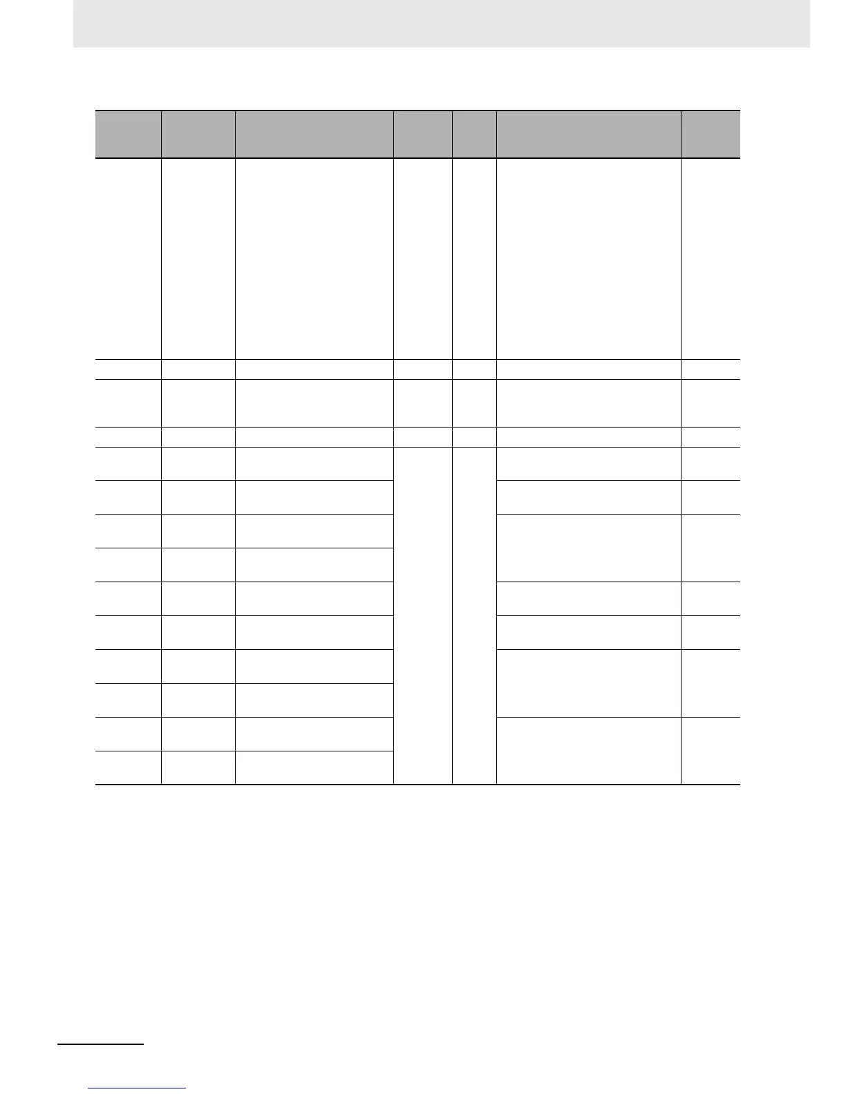
Register
No.
Modbus
register
spec. No.
Function name
Parameter
No.
R/W Monitor or setting data
Resolution
0005 hex 0004 hex Inverter Status C – R
0: –
1: Stop
2: Deceleration
3: Constant speed
4: Acceleration
5: Forward
6: Reverse
7: Forward to reverse
8: Reverse to forward
9: Forward run start
10: Reverse run start
–
0006 hex 0005 hex PID Feedback Value Monitor – R/W 0 to 10000 0.01 [%]
0007 hex
to
0010 hex
– Not used – – – –
0011 hex 0010 hex Fault Counter d080 R 0 to 65530 1 [time]
0012 hex 0011 hex Fault Monitor 1 Factor
d081 R
Refer to Inverter Fault Monitor
Factor List on page 8-34.
–
0013 hex 0012 hex
Fault Monitor 1 Inverter
Status
Refer to Inverter Fault Monitor
Factor List on page 8-34.
–
0014 hex 0013 hex
Fault Monitor 1 Output
Frequency (HIGH)
0 to 40000 0.01 [Hz]
0015 hex 0014 hex
Fault Monitor 1 Output
Frequency (LOW)
0016 hex 0015 hex
Fault Monitor 1 Output
Current
Output current value at the time
of trip
0.1 [A]
0017 hex 0016 hex
Fault Monitor 1 Main Circuit
DC Voltage
DC input voltage at the time of
trip
1 [V]
0018 hex 0017 hex
Fault Monitor 1 Total RUN
Time (HIGH)
Total RUN time before the trip 1 [h]
0019 hex 0018 hex
Fault Monitor 1 Total RUN
Time (LOW)
001A hex 0019 hex
Fault Monitor 1 Total Power
ON Time (HIGH)
Total power ON time before the
trip
1 [h]
001B hex 001A hex
Fault Monitor 1 Total Power
ON Time (LOW)