6 Vector Control
6 - 14
High-function General-purpose Inverter 3G3RX-V1 User’s Manual (I578-E1)
• To use the 0-Hz sensorless vector control method, perform offline auto-tuning. If you cannot perform
offline auto-tuning, set the motor parameters appropriately according to 6-2-4 Motor Parameter
Settings on page 6-11.
• The inverter may not provide sufficient performance characteristics if your motor is two or more sizes
smaller than the maximum applicable motor capacity. This is because the inverter requires a current
accuracy of at least 50% of the rated current.
• If the sensorless vector control method does not provide the intended performance characteristics,
adjust the appropriate motor parameter depending on the phenomenon, as shown in the following
table.
• Be sure to set the Carrier Frequency (b083) to 2.1 kHz or higher. The inverter will not operate
normally at 2.1 Hz or lower.
• To use a motor one size smaller in capacity than the inverter, set the Torque Limit 1 to 4 (b041
to b044) to the value calculated by using the following formula. Be sure that the value α is not
more than 200%. Otherwise, the motor may burn out.
α = Torque Limit set value x (Inverter capacity) / (Motor capacity)
Example
To result in α = 200% when the inverter capacity is 0.75 kW and the motor capacity is 0.4 kW,
according to the above formula, the Torque Limit set value (b041 to b044) can be calculated as
follows: α x (Motor capacity) / (Inverter capacity) = 200% x (0.4 kW) / (0.75 kW) = 106%.
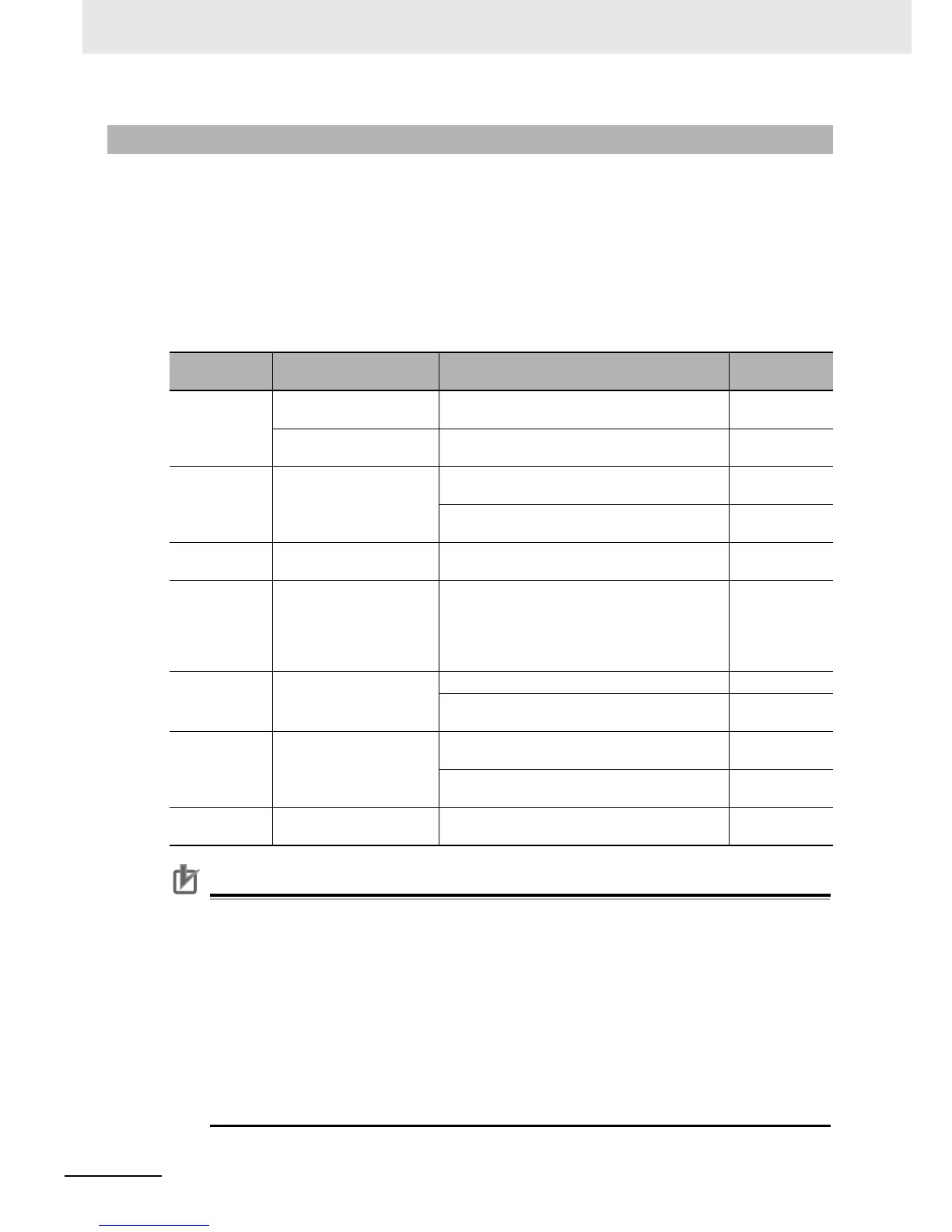
6-2-6 Adjustment for 0 Hz Sensorless Vector Control
Operation
status
Phenomenon Adjustment method
Adjustment
item
Power running
Actual motor speed is
lower than target speed.
Increase the Motor Parameter R2 value
gradually, up to 120% of the set value.
H021/H221/
H031/H231
Actual motor speed is
higher than target speed.
Decrease the Motor Parameter R2 value
gradually, up to 80% of the set value.
H021/H221/
H031/H231
Regeneration
Torque is insufficient at
low frequencies (at 1 to
3 Hz).
Increase the Motor Parameter R1 value
gradually, up to 120% of the set value.
H020/H220/
H030/H230
Increase the Motor Parameter Io value
gradually, up to 120% of the set value.
H023/H223/
H033/H233
During startup
Shock occurs during
startup.
Decrease the Motor Parameter J value
gradually, relative to the set value.
H024/H224/
H034/H234
During
low-speed
startup
Workpiece falls when
brake is released during
low-speed startup.
Increase the Limit at 0 Hz value, up to 150% of
the rated current of the inverter.
If the workpiece falls only at the moment when
the brake is released, increase the Boost
Amount at SLV Startup value.
H060/H260
H061/H261
During
deceleration
Motor is hunting.
Decrease the Speed Response value. H005/H205
Decrease the Motor Parameter J value
gradually, relative to the set value.
H024/H224/
H034/H234
Immediately
after
deceleration
Overcurrent or
overvoltage protection
error occurs.
Decrease the Motor Parameter Io value
gradually, up to 80% of the set value.
H023/H223/
H033/H233
Set the AVR Selection (A081) value to 00
(Always ON) or 01 (Always OFF).
A081
Low-frequency
operation
Rotation is unstable.
Increase the Motor Parameter J value, relative
to the set value.
H024/H224/
H034/H234