• Before wiring, make sure that the charge indicator is not lit.
• Once the power supply is turned on, the capacitor in the inverter remains charged with a high
voltage for a while after the power supply is shut off regardless of whether the inverter
operates or not, which is dangerous.
• If you change cable connections after the power supply is shut off, wait for at least 10 minutes
and, before wiring, check with a circuit tester etc. to be sure that there is no residual voltage
between terminals P/+2 and N/–.
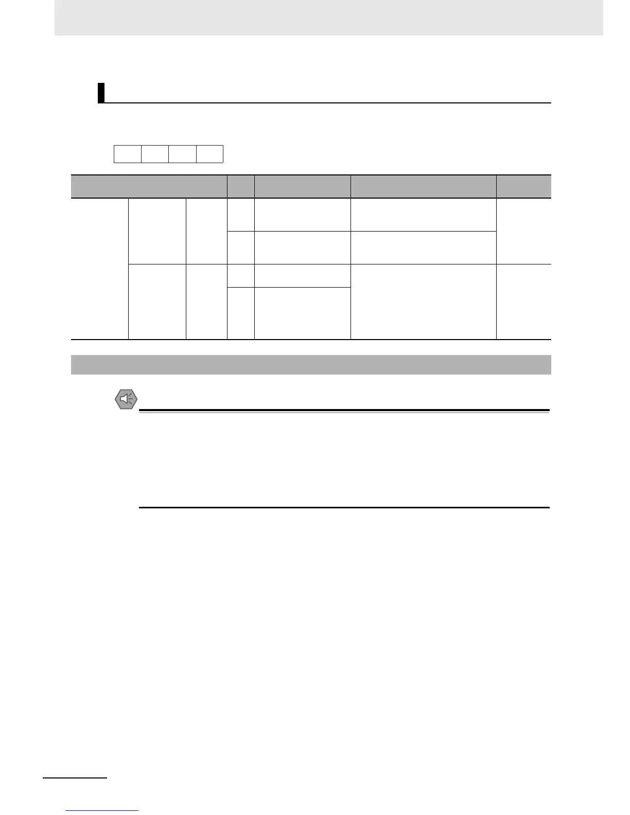
RS-485 Communications Terminal Block
Terminal
Terminal
symbol
Terminal name Description
Specifications
Communication
function
Communications
Signal
RS+
RS485 communications
send/receive terminal,
positive side
Positive side send/receive signal for
RS485 communications.
Conform to
RS485 signal
level
RS–
RS485 communications
send/receive terminal,
negative side
Negative-side send/receive signal for
RS485 communications.
Termination Termination
RP
Terminating Resistor
enable terminal
The RP terminal is used to enable the
built-in Terminating Resistor.
Connect this terminal to the negative
side RS485 communications
send/receive terminal (for Termination
Resistor connection) to enable the
built-in Terminating Resistor.
100 Ω
RS–
RS485 communications
send/receive terminal,
negative side
(for Terminating Resistor
connection)
2-3-4 Wiring for Main Circuit Terminals