2 - 21
2 Design
High-function General-purpose Inverter 3G3RX-V1 User’s Manual (I578-E1)
2-3 Wiring
2
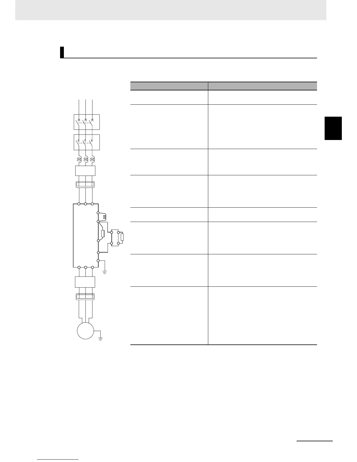
2-3-4 Wiring for Main Circuit Terminals
The diagram below shows the configuration of the inverter main circuit. The function of each peripheral
component is also described.
Main Circuit Configuration Diagram
Name Function
(a) (b) (c) Refer to Recommended Cable Size, Wiring
Device, and Crimp Terminal on page 2-26.
(d) AC reactor This is used as a harmonic suppression
measure. It also helps improve the power factor.
The AC reactor is used when the power supply
voltage unbalance factor is 3% or more, the
inverter capacity is 500 kVA or more, or rapid
change in the power supply voltage occurs to
reduce its effect.
(e) Input noise filter This filter reduces the conductive noise
generated in the inverter and transmitted via
wires. Connect it to the primary side (input side)
of the inverter.
(f) Radio noise filter The inverter in operation may cause noise
through the power supply wiring etc., which
could affect radio receivers or other equipment
nearby. This filter reduces such noise (radiated
noise).
(g) DC reactor This reactor helps suppress harmonics
generated by the inverter.
(h) Braking Resistor
(i) Regenerative braking unit
These are used to increase the inverter’s
braking torque in applications where the signal
turns ON/OFF frequently in a repetitive manner
or where the speed of a load with a large
moment of inertia is decelerated.
(j) Output noise filter This filter is installed between the inverter and
the motor to reduce the radiated noise emitted
from cables. It is used to reduce radio and
television interference and prevent meter and
sensor malfunction.
(k) Radio noise filter This filter is used to reduce noise generated on
the input or output side of the inverter.