2 - 15
2 Design
High-function General-purpose Inverter 3G3RX-V1 User’s Manual (I578-E1)
2-3 Wiring
2
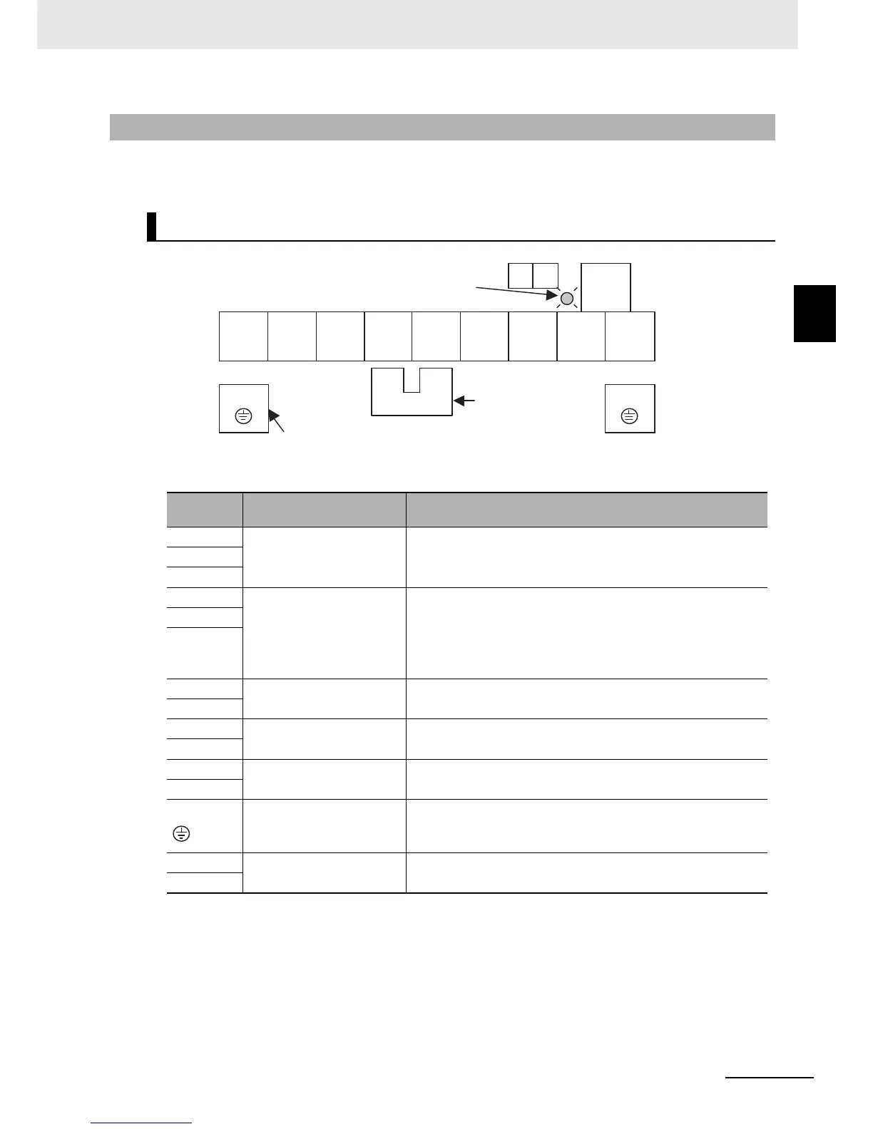
2-3-2 Arrangement and Function of Main Circuit Terminal Block
The table below shows the arrangement of the main circuit terminal block and description of each
terminal.
2-3-2 Arrangement and Function of Main Circuit Terminal Block
Main Circuit Terminal Block
Terminal
symbol
Terminal name Description
R/L1
Main power supply input
terminal
Connect the input power supply.
200-V class: 170 to 264 VAC, 50/60 Hz ±5%
400-V class: 323 to 528 VAC, 50/60 Hz ±5%
S/L2
T/L3
U/T1
Inverter output terminal
Connect a 3-phase motor.
The maximum output voltage depends on the input power supply
voltage.
200-V class: 170 to 264 VAC
400-V class: 323 to 528 VAC
V/T2
W/T3
+1
External DC reactor terminal
Remove the short-circuit bar between the terminals +1 and P/+2,
and connect the optional power factor improvement DC reactor.
P/+2
P/+2
Braking resistor connection
terminal
Connect optional external braking resistors. The terminal RB is
provided for the inverters with 22 kW or lower capacity.
RB
P/+2
Regenerative braking unit
connection terminal
Connect optional regenerative braking units.
N/–
G
Ground terminal
The inverter’s ground terminal. Connect this terminal to the
ground.
Class D (200-V class), Class C (400-V class)
Ro
Control circuit power supply
terminal
Power supply terminals for inverter control circuit.
To
Ro To
RB
R/L1 S/L2 T/L3 +1
P/+2 N/- U/T1 V/T2 W/T3
G
G
+1–P/+2 short-circuit bar
Charge indicator
Ground terminal with short-circuit
bar (shaded area) for EMC filter
function switching
When not using the DC
reactor, keep the
+1–P/+2 short-circuit bar
attached.