5 - 59
5 Basic Settings
High-function General-purpose Inverter 3G3RX-V1 User’s Manual (I578-E1)
5-10 Multi-function Output Settings
5
5-10-1 Multi-function Output Selection
5-10 Multi-function Output Settings
• Use this function to allocate the functions listed below to the multi-function output P1 to P5 terminals
and the multi-function relay output (MA, MB) terminals.
• The multi-function output P1 to P5 terminals are for open collector output and the multi-function relay
output (MA, MB) terminals are for relay output.
• Set the desired function in the Multi-function Output P1 Selection (C021 to C025) and the
Multi-function Relay Output (MA, MB) Function Selection (C026).
• If the alarm code output function is enabled in Alarm Code Selection (C062) (Alarm Code Output
(AC0 to AC3) on page 7-130), some multi-function output settings to select alarm code output are
disabled.
When C062 is set to 01 (3 bits), the output terminals P1 to P3 are used for alarm code output; when
C062 is set to 02 (4 bits), the output terminals P1 to P4 are used for alarm code output.
• This section describes seven types of primary functions. For other functions, refer to 7-5
Multi-function Terminal Functions (Group C) on page 7-108.
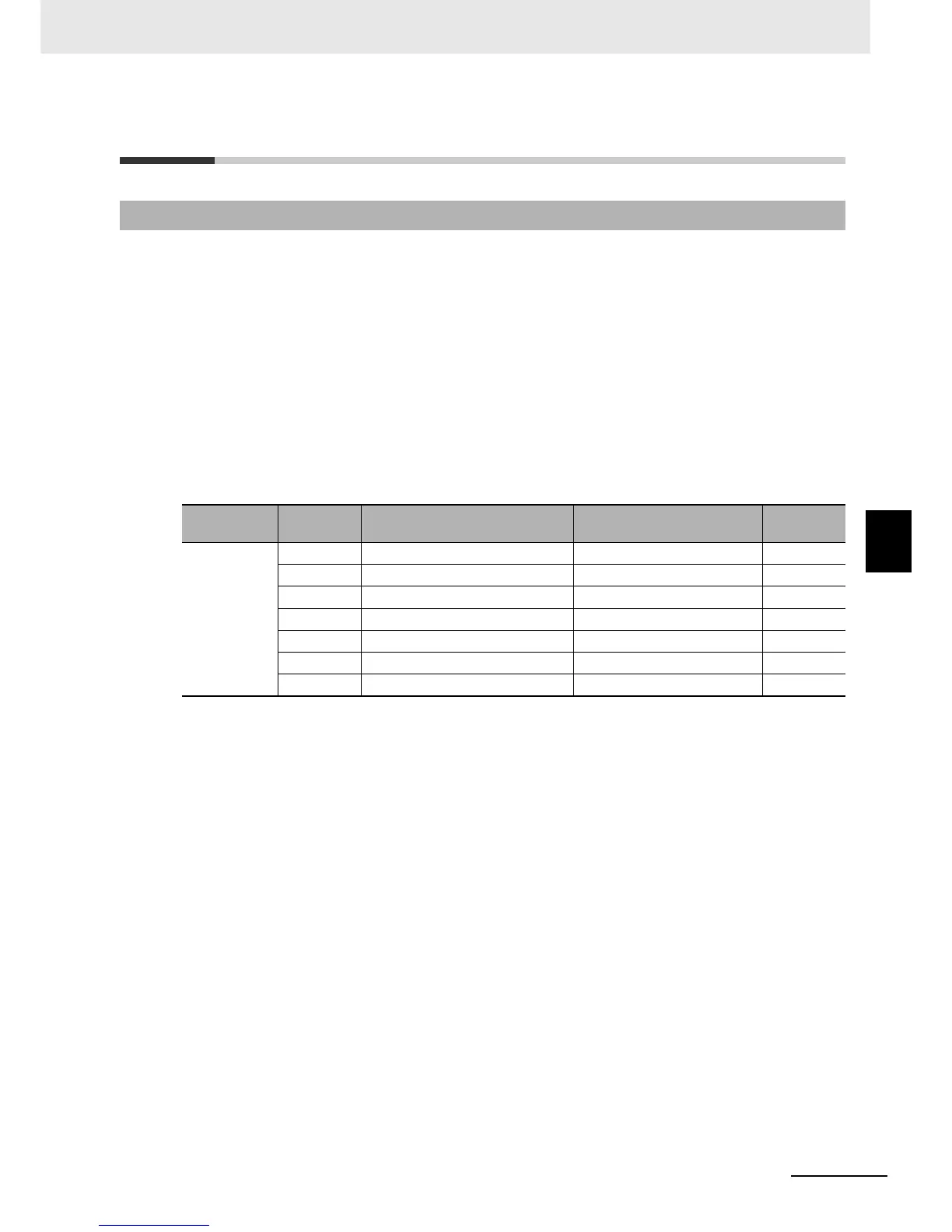
5-10-1 Multi-function Output Selection
Parameter
No.
Data Function name Reference item Page
C021 to C025,
C026
00 RUN: During RUN signal During RUN signal 5-61
01 FA1: Constant speed arrival signal Frequency arrival signal 5-61
05 AL: Alarm signal Alarm signal 5-62
21 ZS: 0-Hz detection signal 0-Hz detection signal 5-63
50 IRDY: Operation ready Operation ready signal 5-63
51 FWR: Forward run signal Forward run signal 5-64
52 RVR: Reverse run signal Reverse run signal 5-64