The reset function clears calculated electronic thermal function data, calculated regenerative
braking usage rate data, and other data.
Therefore, if the reset function is often used, the motor overload protection and braking resistor
overheat protection cannot be performed properly.
If you need to execute the reset function more than once, provide a few minutes of interval
between each execution.
To shut off the inverter output, use the free-run stop function, instead of the reset function.
• In the Reset Restart Selection (C103), select the restart method after trip reset is executed.
• To reset via the control circuit terminal block, set the Multi-function Input S1 to S8 Selection (C008) to
18 (RS: Reset).
• After the reset signal is input and the motor falls in a free-run state, a large residual voltage remains
between motor terminals.
If the inverter restarts the output, an overcurrent may occur.
To circumvent this, set the Restart Standby Time (b003) to a large value (at least 0.3 s).
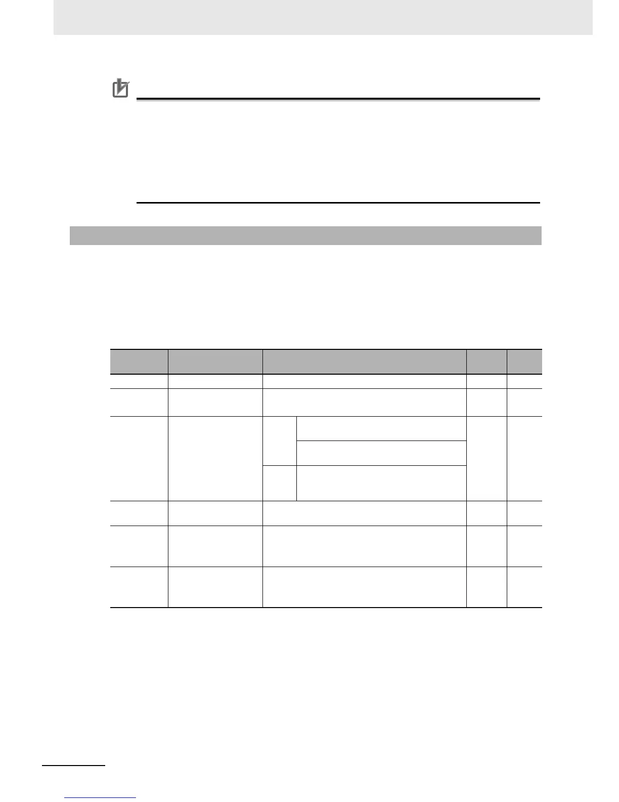
5-8-2 Restart after Resetting
Parameter
No.
Function name Data
Default
data
Unit
b003 Restart Standby Time 0.3 to 100.0 1.0 s
b007
Frequency Matching
Lower Limit Frequency
0.00 to 99.99
100.0 to 400.0
0.00 Hz
b028
Frequency Pull-in
Restart Level
Heavy
load
(CT)
0.20 x Rated current to 2.00 x Rated
current (0.4 to 55 kW)
Rated
current
value
A
0.20 x Rated current to 1.80 x Rated
current (75 to 132 kW)
Light
load
(VT)
0.20 x Rated current to 1.50 x Rated
current
b029
Frequency Pull-in
Restart Parameter
0.10 to 30.00 0.50 s
b030
Starting Frequency
Selection at Frequency
Pull-in Restart
00: Frequency at shutoff
01: Max. frequency
02: Set frequency
00 –
C103
Reset Restart
Selection
00: 0-Hz restart
01: Frequency matching restart (Example 1)
02: Frequency pull-in restart (Example 2)
00 –