2 Design
2 - 56
High-function General-purpose Inverter 3G3RX-V1 User’s Manual (I578-E1)
The built-in slide switch is used to enable or disable the emergency shutoff function.
This function is disabled by factory default.
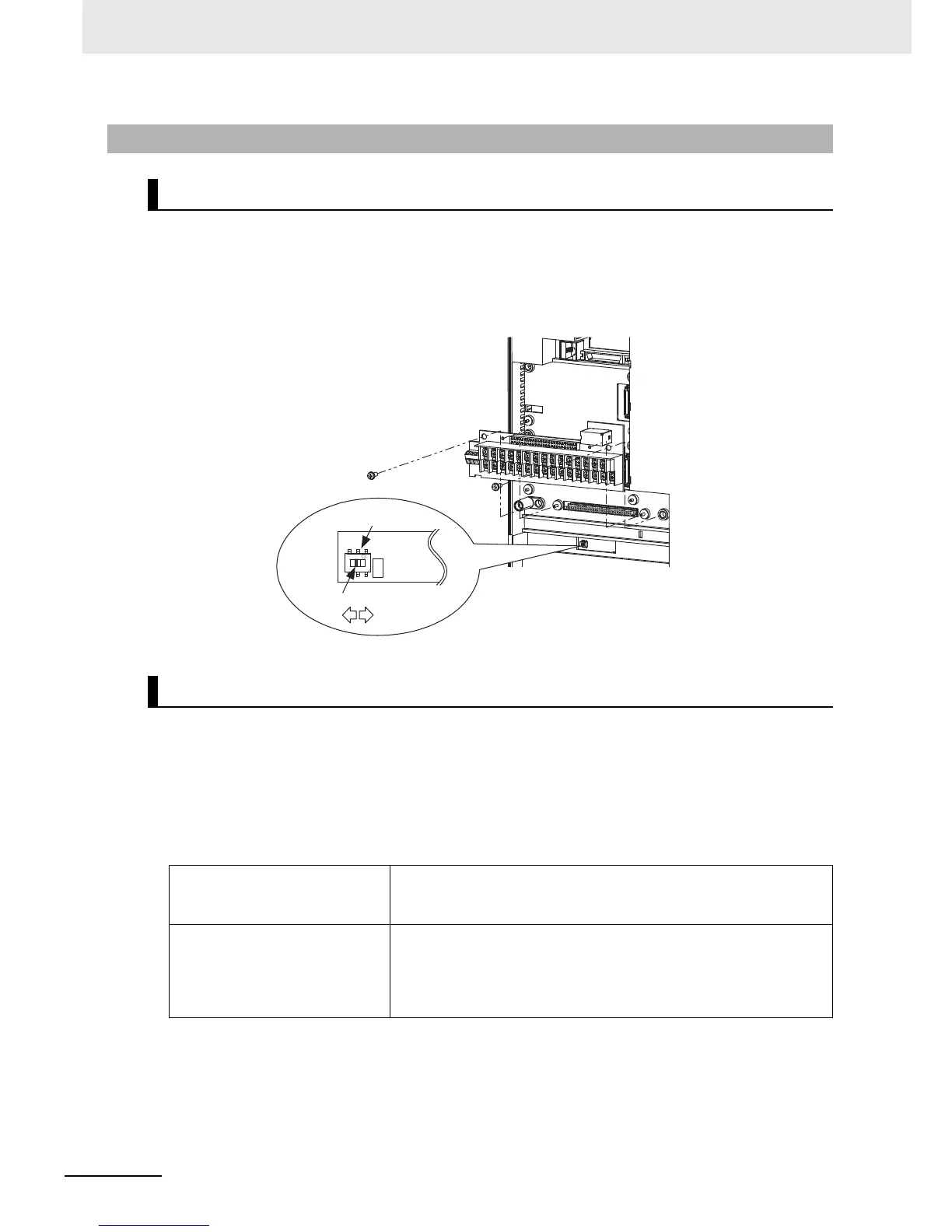
For the location of the slide switch, refer to the figure below.
For how to remove the control circuit terminal block, refer to Removing Control Circuit Terminal Block on
page 2-12.
This function is intended to shut off the inverter output (stop switching the main element) via only the
multi-function input terminal of the hardware circuit without use of the built-in CPU software.
To enable this function, set the slide switch SW1 lever in the inverter to ON. By factory default, slide
switch SW1 is OFF (function disabled).
When this function is enabled, the multi-function input terminals S1 and S3 are dedicated for this
function. No other function can be allocated to these terminals. If another function is allocated, it is
automatically disabled, and terminals S1 and S3 are changed to the emergency shutoff terminals.
2-3-9 Wiring for Emergency Shutoff Function
Slide Switch (SW1) Setting
Emergency Shutoff Function
Special function of multi-function
input terminal S1 when SW1 is
ON
Reset signal (RS)/NO contact (Fixed)
This signal is used to reset the inverter, and to reset the
emergency shutoff trip (E37.*).
Special function of multi-function
input terminal S3 when SW1 is
ON
Emergency shutoff signal (EMR)/NC contact (Fixed)
This signal is used to turn off the inverter output without using the
built-in CPU.
With this signal input, the inverter activates an emergency shutoff
trip (E37.*).