6 - 17
6 Vector Control
High-function General-purpose Inverter 3G3RX-V1 User’s Manual (I578-E1)
6-3 Sensor Vector Control
6
6-3-3 PG Board Function Settings
• Set the number of actual encoder pulses in the Number of Encoder Pulses (P011). In P011, set the
number of pulses (after x1 multiplication).
• Allocate one of the Multi-function Input S1 to S8 Selection (C001 to C008) to 22 (DSE) to output the
excessive speed deviation signal.
• In the Speed Deviation Excessive Level (P027), set the level of excessive deviation. The DSE signal
turns ON when the deviation between the real frequency and the reference frequency becomes equal
to or greater than the P027 value. However, the inverter does not detect this as a trip error.
• Use this function for equipment that cannot be directly coupled to the encoder motor shaft, which
uses a reduction gear system between the motor and the encoder.
• Set the number of actual encoder pulses in the Number of Encoder Pulses (P011).
• In the Motor Gear Ratio Numerator/Denominator (P028/P029), set the reduction ratio of the motor to
the encoder.
These settings convert the set number of encoder pulses into the motor-shaft conversion and
generate the resulting number of pulses in the inverter.
This allows the inverter to detect the speed/position based on the motor-shaft conversion number of
encoder pulses.
Note Be sure to set the numerator and the denominator so that the following condition is met: 1/50 ≤ N/D ≤ 20.
(N: Motor gear ratio numerator, D: Motor gear ratio denominator)
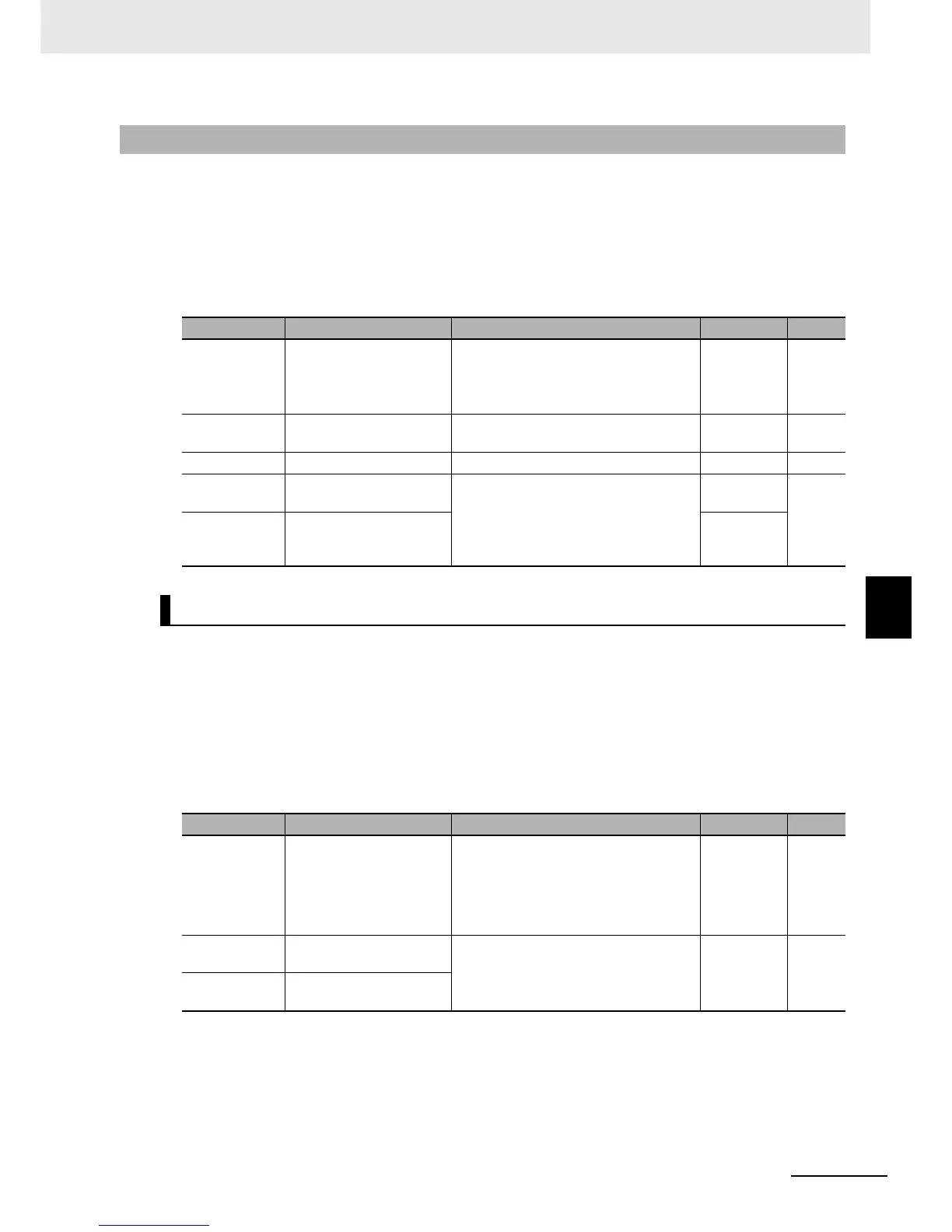
6-3-3 PG Board Function Settings
Parameter No. Function name Data Default data Unit
P011
Number of Encoder
Pulses
128 to 9999.
1000 to 6553 (10000 to 65535):
Set the number of actual encoder
pulses.
1024 pulse
P027
Speed Deviation
Excessive Level
0.00 to 99.99, 100.0 to 120.0:
DSE signal output level
7.50 Hz
H004 1st Motor Pole Number 2/4/6/8/10 4 pole
C021 to C025
Multi-function Output P1
to P5 Selection
22: DSE (Excessive speed deviation)
–
–
C026
Multi-function Relay
Output (MA, MB) Function
Selection
05
Motor Gear Ratio Setting Function
Parameter No. Function name Data Default data Unit
P011
Number of Encoder
Pulses
128. to 9999.
1000 to 6553
(10000 to 65535)
Set the number of actual encoder
pulses.
1024. pulse
P028
Motor Gear Ratio
Numerator
0. to 9999
Set the rotation ratio of the motor to the
encoder.
1. –
P029
Motor Gear Ratio
Denominator