2 Design
2 - 22
High-function General-purpose Inverter 3G3RX-V1 User’s Manual (I578-E1)
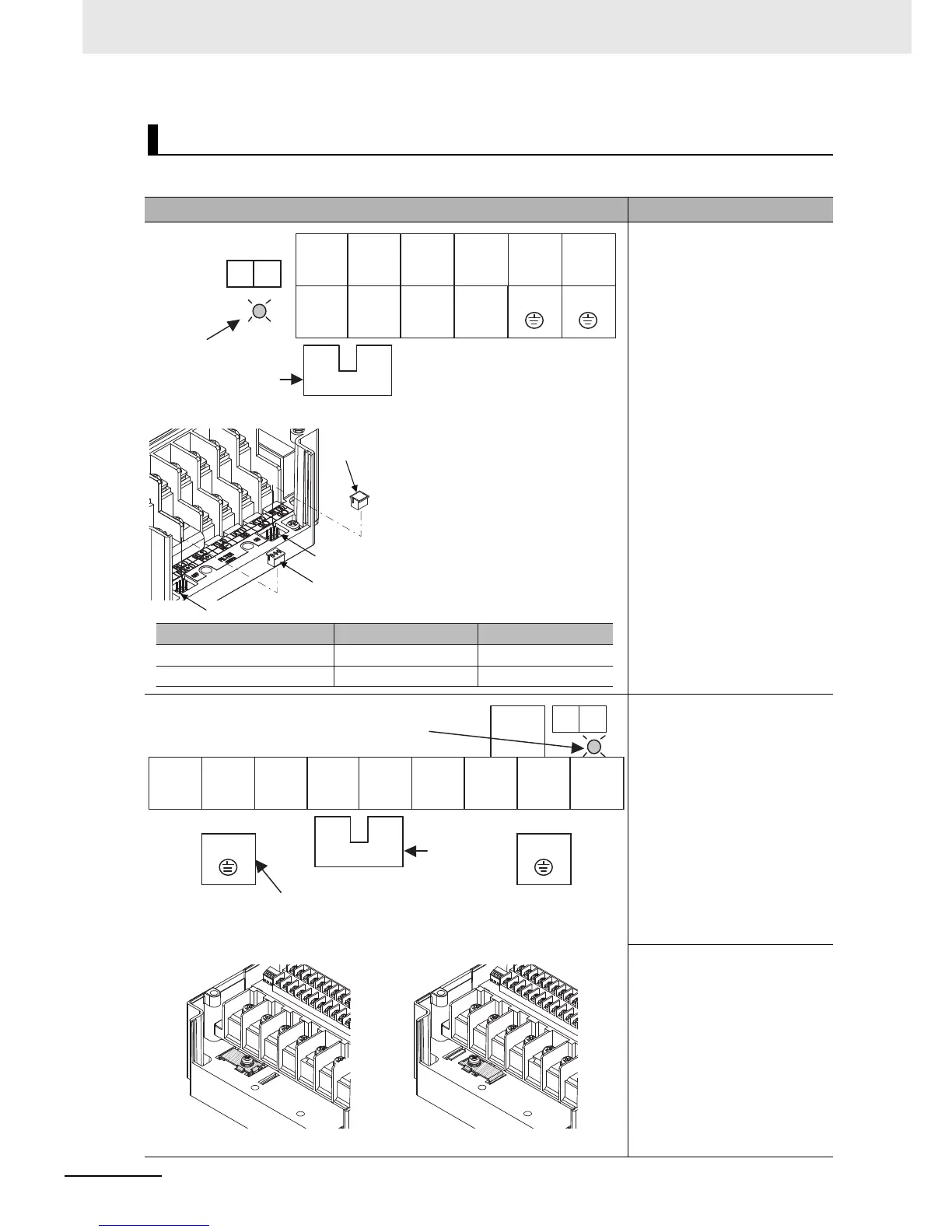
The arrangement of the inverter main circuit terminals is shown below.
Arrangement of Main Circuit Terminals
Terminal arrangement Applicable model
3G3RX-A2004-V1 to A2037-V1
3G3RX-A4004-V1 to A4037-V1
Ro, To: M4
Ground terminal: M4
Others: M4
[EMC filter function switching method]
3G3RX-A2055-V1, A2075-V1
3G3RX-A4055-V1, A4075-V1
Ro, To: M4
Ground terminal: M5
Others: M5
[EMC filter function switching method] 3G3RX-A2110-V1
3G3RX-A4110-V1
Ro, To: M4
Ground terminal: M5
Others: M6
RB
Ro To
G G
Charge indicator
+1–P/+2
short-circuit bar
R/L1 S/L2 T/L3
+1
P/+2 N/–
U/T1 V/T2 W/T3
When not using the DC reactor,
keep the +1–P/+2 short-circuit
bar attached.
Dummy plug
(green)
Filter disable pin (J62)
Filter enable
pin (J61)
Short plug
In order to enable the EMC filter
function, set up the plug inserted into
the filter enable pin (J61) and filter
disable pin (J62) as shown in the
table below. Confirm that electrical
power is disconnected before
performing this setup. Not doing so
may result in electric shock. Also,
use with the plug inserted.
Filter enable pin (J61)
EMC filter disabled (factory setting)
EMC filter enabled
Dummy plug (green)
Dummy plug (green)
Short plug
Short plug
Filter disable pin (J62)
RB
Ro To
G
G
Charge indicator
+1–P/+2
short-circuit bar
R/L1 S/L2 T/L3 +1
P/+2 N/– U/T1 V/T2 W/T3
Ground terminal with
short-circuit bar (shaded area)
for EMC filter function switching
When not using the DC reactor,
keep the +1–P/+2 short-circuit
bar attached.
EMC filter enabled EMC filter disabled (factory setting)