2 - 19
2 Design
High-function General-purpose Inverter 3G3RX-V1 User’s Manual (I578-E1)
2-3 Wiring
2
2-3-3 Arrangement and Function of Control Circuit Terminal Block
The relay output terminals are allocated to 05 (AL: Alarm output) by default. However, the relay
output status of the inverter when the input power supply is OFF is different from the previous
model (3G3
V Series).
The table below shows the relationship between the relay output status when the inverter input
power supply is ON/OFF and the Multi-function Relay Output (MA, MB) Operation Selection
(C036) setting. Select the parameter setting appropriate to the sequence of your inverter
according to this table.
Note Set C036 to 00 to have the same relay output status as with the previous model (3G3V Series).
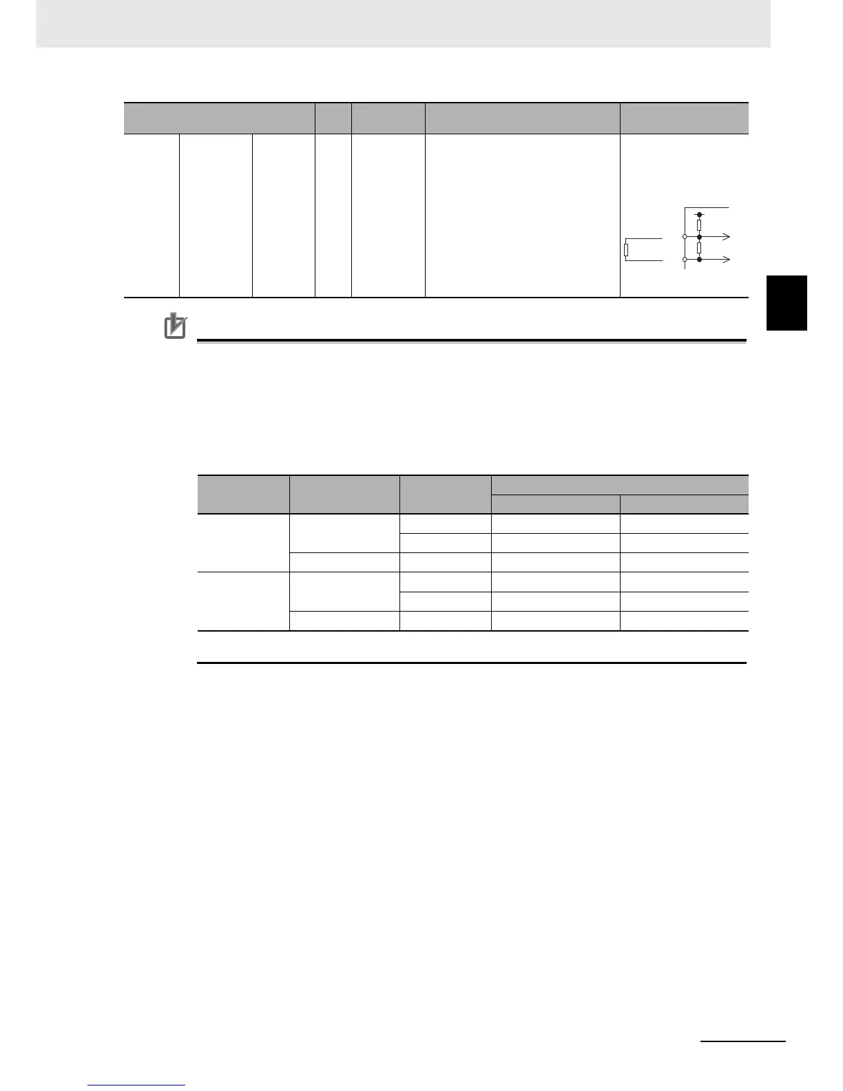
Analog Analog input Sensor TH
External
thermistor
input terminal
Connect an external thermistor to this
terminal, to cause the inverter to trip
when a temperature error occurs. The
terminal SC functions as the common
terminal.
[Recommended thermistor
characteristics]
Allowable rated power: 100 mW min.
Impedance at temperature error: 3 kΩ
Temperature error detection level is
adjustable between 0 and 9999 Ω.
Allowable input voltage
range: 0 to 8 VDC
[Input circuit]
Setting in
C036
Input power
supply
Inverter status
Relay output status
Between MA and MC Between MB and MC
00 ON Normal Open Closed
Alarm output Closed Open
OFF – Open Closed
01
(Default data)
ON Normal Closed Open
Alarm output Open Closed
OFF – Open Closed
Terminal
Terminal
symbol
Terminal
name
Description Specifications
 Loading...


